Dual-CPE SD-WAN
Every other redundancy guide in this section — WAN Failover, Dual-WAN SD-WAN, Dual-Hub SD-WAN — protects against a link, ISP, or hub failure while assuming the branch router itself keeps running. Dual-CPE covers the remaining failure domain: the branch router's own hardware or software. Two independent physical routers are deployed at the same branch site, with VRRP providing LAN-side gateway redundancy — if the active router fails outright (power loss, hardware fault, crash), the standby router takes over as the default gateway with no reconfiguration needed on any LAN client.
This guide focuses specifically on that local hardware-redundancy layer. It is designed to be combined with the WAN- and hub-redundancy guides above, not used as a substitute for them — see Combining with Other SD-WAN Use Cases below.
Overview
How It Works
- Two branch routers ("CPEs") are installed at the same site, each with its own WAN uplink(s) and its own SD-WAN VPN tunnel(s) to the hub.
- On the LAN side, both routers participate in the same VRRP group, sharing a Virtual IP (VIP). LAN clients use the VIP as their default gateway, so they never need to know which physical router is currently active.
- One router holds the VIP as VRRP MASTER and forwards all LAN traffic; the other stays in BACKUP, ready to take over. See VRRP (High Availability) for the full election, advertisement, and failover mechanics.
- Because each CPE independently maintains its own WAN and VPN tunnel, failing over to the BACKUP router also means failing over to that router's WAN path and VPN tunnel — this is what makes Dual-CPE meaningfully different from VRRP alone on a single router with dual links (which only protects the LAN gateway, not the WAN/VPN stack behind it).
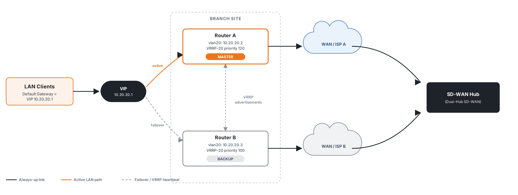
Each router's WAN uplink and VPN tunnel are independent — Router A failing does not take Router B's WAN or VPN tunnel down with it, and vice versa.
Active/Standby vs Active/Active
| Mode | LAN Design | Behavior |
|---|---|---|
| Active/Standby | Single VLAN, single VRRP group | One router carries all LAN traffic; the other is fully idle until failover. Simplest to deploy and reason about. |
| Active/Active (load sharing) | Multiple VLANs, one VRRP group per VLAN, priorities mirrored between routers | Both routers carry live traffic simultaneously — each is MASTER for a subset of VLANs and BACKUP for the rest. Better hardware utilization; if either router fails, the survivor picks up every VLAN. |
Combining with Other SD-WAN Use Cases
Dual-CPE only addresses branch router failure. It says nothing about what happens if a CPE's own WAN link, ISP, or hub goes down while that CPE is otherwise healthy — that is exactly what the other SD-WAN use cases cover, and each one applies independently, per CPE, without any conflict with VRRP:
| Use Case | Protects Against | How It Combines |
|---|---|---|
| WAN Failover / Multi-WAN | A single CPE's own ISP link failing | Configure independently on each CPE — Router A can run its own Multi-WAN across two local links, completely independent of Router B doing the same |
| Dual-WAN SD-WAN | ISP link failure while keeping one stable VPN tunnel per CPE | Each CPE runs its own dual-WAN + single-tunnel design; VRRP on top decides which CPE's tunnel currently carries LAN traffic |
| Dual-Hub SD-WAN | The hub/data-center side failing | Each CPE independently peers with both hubs; a hub failure is invisible to VRRP — it's handled entirely within each CPE's own dual-hub logic |
Tip
A fully redundant branch typically stacks all three layers: each CPE runs Dual-WAN (or Multi-WAN) for its own link redundancy, each CPE peers with both hubs via Dual-Hub SD-WAN, and Dual-CPE's VRRP layer sits on top to survive the loss of an entire router. Each layer is configured and verified independently — there is no special interaction to configure between them.
Preventing Asymmetric Return Routing (BGP AS-Path Prepend)
There is one interaction that does need explicit configuration. When Dual-CPE is combined with an SD-WAN overlay (e.g. Dual-Hub SD-WAN), each CPE runs its own independent VPN tunnel and BGP session to the hub — and both CPEs advertise the same branch LAN subnet, because it's the same physical LAN and each router keeps its own connected route to it regardless of which one currently holds the VRRP VIP. From the hub's perspective this looks like two equally valid BGP paths to the branch network, so the hub picks whichever wins its own best-path comparison — independently of which CPE VRRP has actually made the active LAN gateway.
If the hub ends up sending return traffic to the CPE that is currently VRRP BACKUP, that CPE doesn't hold the VIP and has no live forwarding path for that traffic — producing intermittent or fully asymmetric connectivity even though both CPEs and both tunnels are individually healthy.
Fix this by making the backup CPE's advertisement of the branch subnet less preferred at the hub, using the same AS-path prepend technique used for ISP-facing multi-homing, applied here to the backup CPE's VPN instance peering instead of an ISP session.
Note
As with other SD-WAN VPN BGP configuration (see VRF over SD-WAN — CLI Reference), this is normally generated and pushed by mfusion. The CLI below is shown for reference and expert troubleshooting.
CLI Reference (Router B — backup CPE, VLAN 20 example from Step 1)
router bgp 65051 vrf 4
 ...
 neighbor 0168_RansNet_SSL3OPENVPN_4 route-map BRANCH-PREPEND out
!
ip prefix-list BRANCH-LAN permit 10.20.20.0/24
!
route-map BRANCH-PREPEND permit 10
 match ip address prefix-list BRANCH-LAN
 set as-path prepend 65051 65051 65051
Key points:
- Apply the prepend route-map only on the backup CPE's VPN instance neighbor — the primary CPE continues advertising the branch subnet normally, with no prepend
- The hub now sees two paths to
10.20.20.0/24: a short, unprepended path via the primary CPE, and an artificially longer path via the backup CPE — and prefers the primary CPE's path for all return traffic under normal conditions - This is a static configuration; it does not need to change on every VRRP failover. If the primary CPE (or its tunnel) goes down entirely, its BGP-advertised route disappears and the hub automatically falls back to the backup CPE's still-advertised path — the prepend only matters while both paths are actually available
- In Active/Active mode (Step 2), apply this per VLAN subnet rather than per CPE: each router should prepend only the subnet(s) where it holds the lower VRRP priority, mirroring the same priority scheme configured for VRRP itself — so hub-side route preference always lines up with whichever CPE is normally MASTER for that VLAN
Use Cases
| Scenario | Business Impact | Solution |
|---|---|---|
| Branch with no on-site IT staff | A single router hardware failure means total outage until a technician can travel on-site to swap hardware | The standby router takes over automatically in under a second; the failed unit can be replaced during a scheduled visit |
| Retail / POS sites | A single router failure halts all point-of-sale and card-payment traffic | VRRP failover keeps the LAN gateway available continuously; combine with Dual-WAN SD-WAN if the site also has two ISPs |
| Firmware upgrade / maintenance windows | Upgrading or rebooting the active router normally causes a brief LAN outage | Fail over to the BACKUP router first (see Verification), then upgrade the now-idle router with zero impact on LAN clients |
| Sites requiring load distribution across two routers | A single router may not have the throughput or session capacity for the whole site | Use Active/Active mode (multiple VLANs, mirrored VRRP priorities) so both routers carry live traffic under normal conditions |
Requirements
- Two RansNet branch-series routers of the same model at the same site, cabled to the same LAN switch/VLAN(s)
- A dedicated VRRP group ID and VIP per VLAN participating in VRRP (must match on both routers)
- Independent WAN connectivity per router (can be a single link each, or a full Multi-WAN/Dual-WAN/Dual-Hub setup per router — see Combining with Other SD-WAN Use Cases)
- If using VRRP tracking, a reachable upstream target IP per router (e.g. a hub loopback, or
8.8.8.8) to detect loss of upstream reachability, not just LAN-side link state
Deployment
Step 1 — Active/Standby: Configure the VRRP Group
Under the LAN VLAN interface on both routers, enable VRRP (High Availability) and add a VRRP group with a matching VRRP ID and Virtual IP, but a higher Priority on the router that should normally be MASTER.
GUI Configuration
Navigate to Device Settings → Network → Interfaces, edit the LAN VLAN interface, enable the VRRP (High Availability) option under Other Settings, and add a VRRP group.
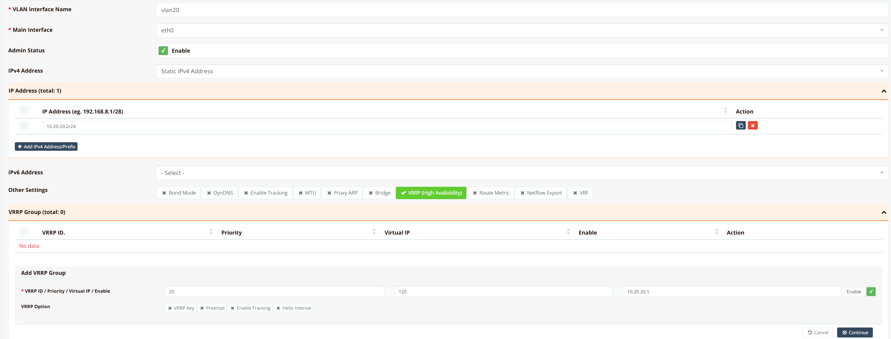
For the full field reference (VRRP ID, Priority, Virtual IP, Authentication), see VRRP — GUI Configuration.
CLI Configuration (Router A — preferred MASTER)
interface vlan 0 20
  enable
  ip address 10.20.20.2/24
  vrrp-group 20
    priority 120
    virtual_ipaddress 10.20.20.1
    enable
CLI Configuration (Router B — BACKUP)
interface vlan 0 20
  enable
  ip address 10.20.20.3/24
  vrrp-group 20
    priority 100
    virtual_ipaddress 10.20.20.1
    enable
Router A's higher priority (120 vs the default 100) makes it the preferred MASTER — it holds the VIP 10.20.20.1 whenever it is healthy.
Step 2 — Active/Active: Load Sharing Across VLANs (Optional)
To use both routers simultaneously instead of leaving one fully idle, split the LAN into multiple VLANs and run a separate VRRP group per VLAN, with priorities mirrored between the two routers:
- Router A — VLAN 10 (VRRP-10, priority
120, MASTER for VLAN 10) and VLAN 20 (VRRP-20, priority100, BACKUP for VLAN 20) - Router B — VLAN 10 (VRRP-10, priority
100, BACKUP for VLAN 10) and VLAN 20 (VRRP-20, priority120, MASTER for VLAN 20)
Each router is MASTER for the VLANs it's configured with the higher priority on, and BACKUP for the rest. If either router fails, the survivor becomes MASTER for every VLAN, so no VLAN loses its gateway. See VRRP — Typical Deployment for the general load-sharing pattern this follows.
Step 3 — Add Upstream Tracking (Recommended)
VRRP alone only detects whether the other router is alive — it does not know if a router's own upstream path has failed while the router itself is still running. Add tracking so a router with a dead upstream link releases the VIP even though it's still physically up.
GUI Configuration
In the same VRRP group, enable Enable Tracking and configure the tracking method.
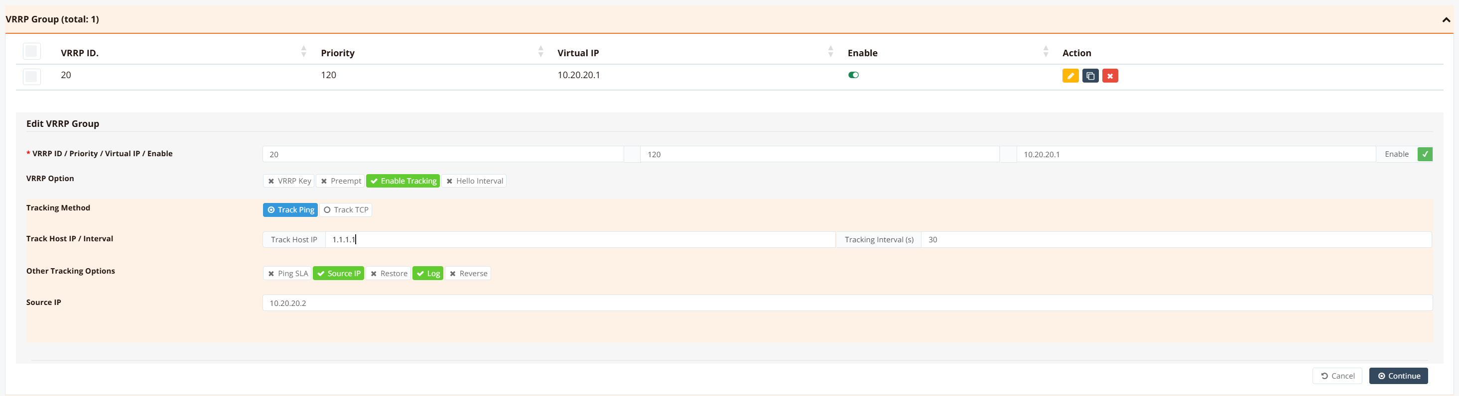
For the full field reference (Track Host IP, Interval, Ping SLA, Source IP, Log, Reverse), see Tracking — Common Options.
CLI Configuration
interface vlan 0 20
  enable
  ip address 10.20.20.2/24
  vrrp-group 20
    priority 120
    virtual_ipaddress 10.20.20.1
    track icmp 1.1.1.1 30 src 10.20.20.2 log
    enable
track icmp 1.1.1.1 30 src 10.20.20.2 log probes 1.1.1.1 every 30 seconds, sourced from 10.20.20.2, and logs every tracking cycle. If the probe fails, this router withdraws from the VRRP group entirely — it stops advertising and releases the VIP if it was MASTER — so the other router takes over even though this router's LAN interface never went down.
Verification
| What to Check | Command | Expected Outcome |
|---|---|---|
| VRRP group state | show ip vrrp |
The MASTER router shows running with the VIP listed; the BACKUP shows running with no VIP (or (backup), see VRRP Verification) |
| VIP presence on the interface | show interface vlan20 |
The MASTER shows the VIP as a secondary IPv4 Address; the BACKUP shows only its own real IP |
| Tracking status | show logging system |
Each tracking cycle logs a pass or fail — see the log examples below |
| Failover behavior | Disconnect the MASTER's WAN/upstream, or power it off | LAN clients regain connectivity within seconds via the VIP, now served by the other router |
Steady state (Router A, MASTER):
XE# show ip vrrp
VRRP_ID Priority        Status          Interface       Interface IP    VRRP_VIP
-------------------------------------------------------------------------------------------------
20      120             running         vlan20          10.20.20.2/24   10.20.20.1/32
XE#
XE# show interface vlan20
================================================================================
  Interface : vlan20
================================================================================

  Network Information
  ----------------------------------------
  Admin State            : UP
  Link State             : UP
  MAC Address            : d4:dd:0b:00:02:08
  MTU                    : 1500 bytes
  IPv4 Address           : 10.20.20.2/24
  IPv4 Broadcast         : 10.20.20.255
  IPv4 Address           : 10.20.20.1/32
  IPv6 Address           : fe80::d6dd:bff:fe00:208/64 [link]

  VLAN Information
  ----------------------------------------
  VLAN ID                : 20
  Parent Interface       : eth0

  Physical Information
  ----------------------------------------
  Link Detected          : yes

================================================================================
XE#
With tracking enabled and log set, show logging system shows a passing cycle every tracking interval:
Wed Aug 26 03:27:24 2026 user.info track_vrrp_20: Wed Aug 26 03:27:24 +08 2026 start tracking VRRP group
Wed Aug 26 03:27:24 2026 user.info track_vrrp_20: tracked host: 1.1.1.1
Wed Aug 26 03:27:24 2026 user.info track_vrrp_20: track source: 10.20.20.2
Wed Aug 26 03:27:24 2026 user.info track_vrrp_20: track method: icmp
Wed Aug 26 03:27:24 2026 user.info track_ping_1.1.1.1: Wed Aug 26 03:27:24 +08 2026 start ping tracking to 1.1.1.1.
Wed Aug 26 03:27:24 2026 user.info track_ping_1.1.1.1: pinging from  (10.20.20.2, vrf=) to 1.1.1.1
Wed Aug 26 03:27:25 2026 user.info track_ping_1.1.1.1: ping to 1.1.1.1 passed.
Wed Aug 26 03:27:25 2026 user.info track_ping_1.1.1.1: Ping tracking to 1.1.1.1 passed.
Wed Aug 26 03:27:25 2026 user.info track_vrrp_20: VRRP 20 tracking passed.
Failover (tracked target becomes unreachable):
Wed Aug 26 03:30:06 2026 user.info track_vrrp_20: Wed Aug 26 03:30:06 +08 2026 start tracking VRRP group
Wed Aug 26 03:30:06 2026 user.info track_vrrp_20: tracked host: 1.1.1.1
Wed Aug 26 03:30:06 2026 user.info track_vrrp_20: track source: 10.20.20.2
Wed Aug 26 03:30:06 2026 user.info track_vrrp_20: track method: icmp
Wed Aug 26 03:30:06 2026 user.info track_ping_1.1.1.1: Wed Aug 26 03:30:06 +08 2026 start ping tracking to 1.1.1.1.
Wed Aug 26 03:30:10 2026 user.info track_ping_1.1.1.1: ping to 1.1.1.1 failed.
Wed Aug 26 03:30:10 2026 user.info track_ping_1.1.1.1: Ping to 1.1.1.1 failed.
Wed Aug 26 03:30:10 2026 user.info track_vrrp_20: VRRP 20 tracking failed.
Wed Aug 26 03:30:10 2026 user.info track_vrrp_20: Stopping VRRP 20.
Router A loses the VIP the moment tracking fails — show ip vrrp now shows stopped with no VIP, and Router B (the surviving router) takes over as MASTER:
XE# show ip vrrp
VRRP_ID Priority        Status          Interface       Interface IP    VRRP_VIP
-------------------------------------------------------------------------------------------------
20      120             stopped         vlan20          10.20.20.2/24   ---
XE#
XE# show interface vlan20
================================================================================
  Interface : vlan20
================================================================================

  Network Information
  ----------------------------------------
  Admin State            : UP
  Link State             : UP
  MAC Address            : d4:dd:0b:00:02:08
  MTU                    : 1500 bytes
  IPv4 Address           : 10.20.20.2/24
  IPv4 Broadcast         : 10.20.20.255
  IPv6 Address           : fe80::d6dd:bff:fe00:208/64 [link]

  VLAN Information
  ----------------------------------------
  VLAN ID                : 20
  Parent Interface       : eth0

  Physical Information
  ----------------------------------------
  Link Detected          : yes

================================================================================
XE#
Note that IPv4 Address : 10.20.20.1/32 (the VIP) is no longer listed once VRRP 20 stops — the interface only shows its own real address.
Troubleshooting
| Symptom | Likely Cause | Solution |
|---|---|---|
| Both routers show as BACKUP with no MASTER | VRRP ID or Virtual IP mismatch between routers, or a firewall blocking multicast 224.0.0.18 between the routers |
Confirm the VRRP ID and Virtual IP are identical on both routers; verify VRRP multicast traffic isn't filtered between them |
| Both routers claim MASTER simultaneously (split-brain) | The routers cannot see each other's VRRP advertisements (LAN switch misconfiguration, VLAN mismatch, or a link between them down) | Check switch port/VLAN configuration between the two routers; confirm both routers are on the same VLAN and can multicast to each other |
| Failover works, but LAN clients don't reach the Internet afterward | The BACKUP router's own WAN link, VPN tunnel, or upstream routing isn't actually healthy | Verify the BACKUP router's WAN/VPN status independently — VRRP only confirms the LAN gateway moved, not that the new MASTER's own uplink works. See WAN Failover or Dual-Hub SD-WAN troubleshooting |
| Router with a dead upstream link still holds the VIP | VRRP tracking is not configured, or the tracked target isn't representative of real upstream health | Add track icmp <target> <interval> to the VRRP group (Step 3); pick a tracked target that reflects real upstream reachability, not just local link state |
| Preferred router doesn't reclaim MASTER after recovering | no preempt was configured (unlikely — preemption is on by default), or its priority is not actually higher |
Confirm preemption is enabled (default) and the intended MASTER's priority is higher than the other router's |
| Return traffic from the hub intermittently arrives at the BACKUP CPE (asymmetric routing) when combined with SD-WAN hub peering | Both CPEs advertise the identical branch LAN subnet to the hub with no BGP preference set between the two paths | AS-path prepend the backup CPE's outbound VPN instance advertisement — see Preventing Asymmetric Return Routing |
Debugging Commands
Best Practices
Resilience
- Use identical hardware and firmware versions on both CPEs to avoid feature or behavior mismatches during failover.
- Always add VRRP tracking to an upstream target (Step 3) — without it, a router with a dead WAN/VPN path but a healthy LAN link will keep holding the VIP, causing a silent outage that VRRP alone cannot detect.
- Test failover deliberately on a schedule (e.g. during a maintenance window) rather than waiting for a real failure to discover a misconfiguration.
- When combining with SD-WAN hub peering, always AS-path prepend the backup CPE's advertisement of the branch subnet — see Preventing Asymmetric Return Routing. Skipping this doesn't break connectivity outright, but leaves return-path selection at the hub up to chance.
Performance
- In Active/Active mode, balance VLAN assignment so each router's normal MASTER load is roughly equal — mirror priorities symmetrically as shown in Step 2.
- Remember that failover moves all traffic (and, if combined with Dual-WAN/Dual-Hub, the WAN and VPN load) onto the surviving router — size both CPEs to handle the full site load alone, not just half of it.
Security
- Set VRRP authentication (MD5 key) identically on both routers to prevent a rogue device on the LAN from joining the VRRP group and hijacking the VIP.
- Restrict management access (SSH, GUI) to LAN on both CPEs — see Device Hardening.
Related Features
- VRRP (High Availability) — full VRRP mechanics, GUI/CLI reference, and load-sharing deployment pattern
- Tracking — Common Options — VRRP tracking field reference
- WAN Failover / Multi-WAN — per-CPE WAN link redundancy
- Dual-WAN SD-WAN — per-CPE WAN redundancy with a single stable VPN tunnel
- Dual-Hub SD-WAN — per-CPE hub/data-center redundancy
- Device Hardening — securing management access on both CPEs