VLAN Steering Over Captive Portal
VLAN Steering is a dynamic VLAN assignment technique that assigns authenticated users to different VLANs based on their user profile or account type. By combining RansNet's captive portal authentication with RADIUS-based VLAN steering, you can route guests, staff, and members to their respective networks on a single SSID — simplifying wireless configuration while enabling per-user network isolation, bandwidth control, and access policies.
RansNet HotSpot Gateway (HSG) includes a built-in RADIUS server that works with standard wireless APs and switches to provide dynamic VLAN assignment. Users authenticate via captive portal (no complex 802.1x supplicant required), and the HSG automatically assigns them to the authorized VLAN based on their access profile.
Overview
How It Works
VLAN Steering correlates a user's login credentials (from the captive portal) with their device MAC address, then instructs the access point to move the device to the appropriate VLAN. Two workflow diagrams illustrate the process:
VLAN Steering Workflow:
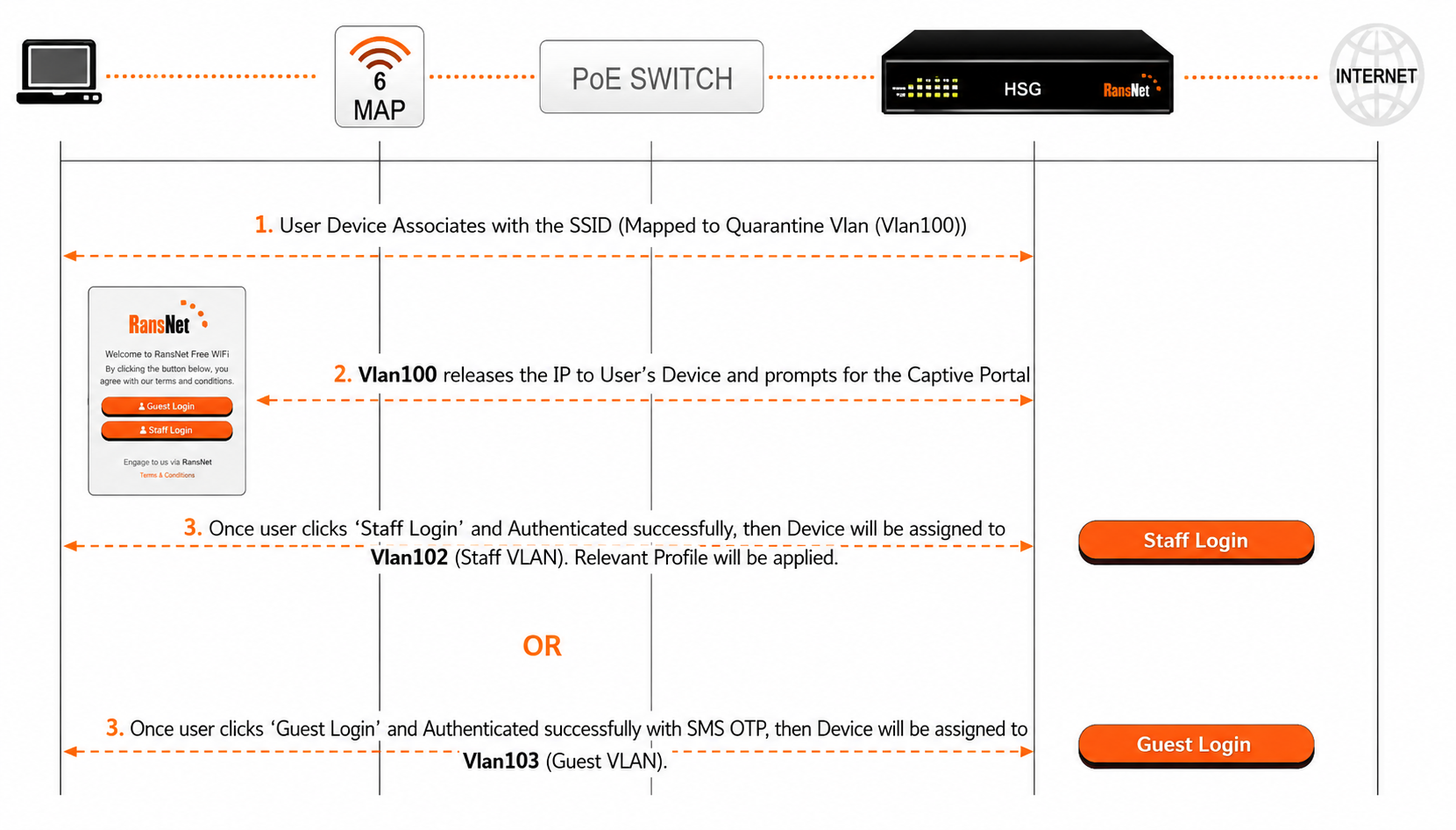
- A new device associates with the SSID (VLAN100, quarantine network)
- Device receives DHCP IP from the quarantine VLAN
- Captive portal login page appears (automatic on mobile devices, manual on others)
- User authenticates (sign-in, self-register, SMS OTP, etc.) using captive portal
- HSG sends RADIUS Vendor-Specific Attribute (VSA) to the AP containing the target VLAN ID
- AP de-authenticates the device from quarantine VLAN and re-associates it to the authorized VLAN
- Device receives new IP from authorized VLAN (no portal re-prompt)
- Authorized traffic bypasses HSG hotspot instance and routes at wire speed through the assigned VLAN
Note
The authorized VLAN does not need to pass through the HSG physically. For example, an upstream UTM firewall can connect directly to the authorized VLAN and handle all authorized user traffic without additional HSG processing.
Live Demo
Watch a live demonstration of VLAN Steering in action:
The demo shows real-world device authentication, VLAN assignment, and traffic isolation in a multi-user hotspot environment.
Use Cases
| Scenario | Benefit |
|---|---|
| Hotels & Accommodations | Create Personal Area Networks (PANs) per guest room. Each guest account maps to a dedicated VLAN (isolated from other guests), yet same-guest devices can communicate within their private PAN across the hotel property. Eliminates per-room cabling and dedicated AP complexity. |
| Enterprises & Offices | Enforce Network Access Control (NAC) for BYOD and visitor devices. One SSID with one captive portal; visitors self-register and get quarantine VLAN, staff login with corporate accounts and get corporate VLAN. Simplifies configuration vs. multiple SSIDs per user type. |
| Institutions & Schools | Segment student, faculty, and guest networks on one SSID. Automatic VLAN assignment based on account type (student ID, faculty login, guest pass) reduces Wi-Fi management overhead. |
| Airports & Stadiums | Reduce HSG CPU load in high-density deployments. Hotspot service handles quarantine VLAN only (initial login); authorized users route at wire speed through their designated VLAN, bypassing HSG. Allows single HSG to serve thousands of concurrent users. |
| Dormitories | Assign per-student subnets for device isolation while allowing multi-device per student. Automatic VLAN steering based on student ID prevents manual per-room configuration. |
Requirements
- HSG appliance — latest firmware version
- Wireless AP or WLC — must support RADIUS Vendor-Specific Attributes (VSA) for VLAN assignment on IEEE 802.11 MAC addresses (MAC-based RADIUS authentication)
- Network switch — must support VLAN tagging (802.1q); all uplink ports configured as trunks permitting all VLANs
- RADIUS shared secret — configured on both HSG and AP for authentication
- VLAN planning — pre-assign VLAN IDs (e.g., 100 for quarantine, 102 for staff, 103 for guests) and corresponding subnets
Topology
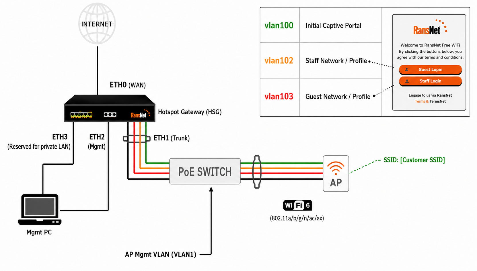
Physical Layout:
- HSG eth0 — connects to ISP (WAN uplink)
- HSG eth1 — connects to managed switch (VLAN trunk)
- Managed Switch — uplinks to HSG via trunk; APs and authorized-VLAN devices attach to access ports
- Wireless AP — connects to switch; authenticates clients against HSG RADIUS server; moves authenticated devices to target VLAN via VSA
- Authorized VLAN — can extend directly to a firewall, UTM, or additional switch without passing through HSG (optional)
Network Subnets:
- VLAN 100 (Quarantine) —
172.16.100.0/24— initial assignment for all new devices; hotspot service enabled - VLAN 102 (Staff) —
172.16.102.0/24— for authenticated staff/members - VLAN 103 (Guest) —
172.16.103.0/24— for authenticated guests - Management VLAN 1 —
192.168.8.0/22— AP and upstream device management
Deployment
Step 1: Physical Setup and AP/Switch Configuration
Physical Connections:
- Connect HSG WAN port (eth0) to ISP modem or fiber ONT
- Connect HSG LAN port (eth1) to managed switch via VLAN trunk port
- Configure all switch uplink ports as trunk mode; permit all VLANs
- Connect wireless AP to switch access port (auto-discover HSG from management VLAN 1 DHCP)
- Connect management PC to HSG eth2 or switch access port
Note
HSG eth2 is pre-configured to serve 10.10.10.0/24 for out-of-band management. Access HSG GUI at 10.10.10.1 for initial setup.
Configure AP/WLC to Use HSG as RADIUS Server:
| Parameter | Value | Notes |
|---|---|---|
| Profile Name | RansNet-HSG-AUTH |
User-defined name for RADIUS configuration |
| Authentication Type | RADIUS |
MAC-based authentication (not 802.1x) |
| RADIUS Server IP | 192.168.8.1 |
HSG management IP on default VLAN 1 |
| RADIUS Port | 1812 |
Standard RADIUS authentication port |
| Shared Secret | testing123 |
Pre-configured on HSG; change in production |
| Accounting Port | 1813 |
Optional; enables session logging |
| Enable VLAN Support | Yes |
AP honors VLAN assignment from RADIUS VSA |
Warning
Change the default shared secret testing123 to a strong passphrase before deploying to production.
Step 2: Configure VLAN and DHCP on HSG
GUI Configuration
Navigate to Device Settings → Network → Interfaces → VLAN and create three new VLANs (100, 102, 103) on physical interface eth1.
VLAN 100 (Quarantine/Untrusted):
| Field | Value | Description |
|---|---|---|
| VLAN Name | vlan100 |
Descriptive name |
| Admin Status | Enabled |
Activate the interface |
| Physical Interface | eth1 |
Parent interface |
| IP Address/Netmask | 172.16.100.1/24 |
Gateway IP for DHCP |
| Hotspot Service | Enable |
Require portal authentication |
VLAN 102 (Staff/Authorized):
| Field | Value | Description |
|---|---|---|
| VLAN Name | vlan102 |
Staff network |
| Admin Status | Enabled |
Activate the interface |
| Physical Interface | eth1 |
Parent interface |
| IP Address/Netmask | 172.16.102.1/24 |
Gateway IP |
| DHCP Server | Enable |
Provide IP addresses |
| DNS Servers | 8.8.8.8 8.8.4.4 |
Public DNS for authorized users |
| Client Default Gateway | 172.16.102.1 |
Route through HSG |
| DHCP Pool Range | 172.16.102.2 – 172.16.102.254 |
Available IPs for clients |
| Lease Time | 86400 |
24-hour lease |
VLAN 103 (Guest/Authorized):
| Field | Value | Description |
|---|---|---|
| VLAN Name | vlan103 |
Guest network |
| Admin Status | Enabled |
Activate the interface |
| Physical Interface | eth1 |
Parent interface |
| IP Address/Netmask | 172.16.103.1/24 |
Gateway IP |
| DHCP Server | Enable |
Provide IP addresses |
| DNS Servers | 8.8.8.8 8.8.4.4 |
Public DNS for guests |
| Client Default Gateway | 172.16.103.1 |
Route through HSG |
| DHCP Pool Range | 172.16.103.2 – 172.16.103.254 |
Available IPs for clients |
| Lease Time | 86400 |
24-hour lease |
CLI Configuration
!
interface vlan 1 100
 description "Quarantine VLAN"
 enable
 ip address 172.16.100.1/24
 dhcp-server
  dns 8.8.8.8 8.8.4.4
  router 172.16.100.1
  lease-time 86400
  range 172.16.100.20 172.16.100.254
  enable
!
interface vlan 1 102
 description "Staff VLAN"
 enable
 ip address 172.16.102.1/24
 dhcp-server
  dns 8.8.8.8 8.8.4.4
  router 172.16.102.1
  lease-time 86400
  range 172.16.102.20 172.16.102.254
  enable
!
interface vlan 1 103
 description "Guest VLAN"
 enable
 ip address 172.16.103.1/24
 dhcp-server
  dns 8.8.8.8 8.8.4.4
  router 172.16.103.1
  lease-time 86400
  range 172.16.103.20 172.16.103.254
  enable
!
Step 3: Create Captive Portal on HSG
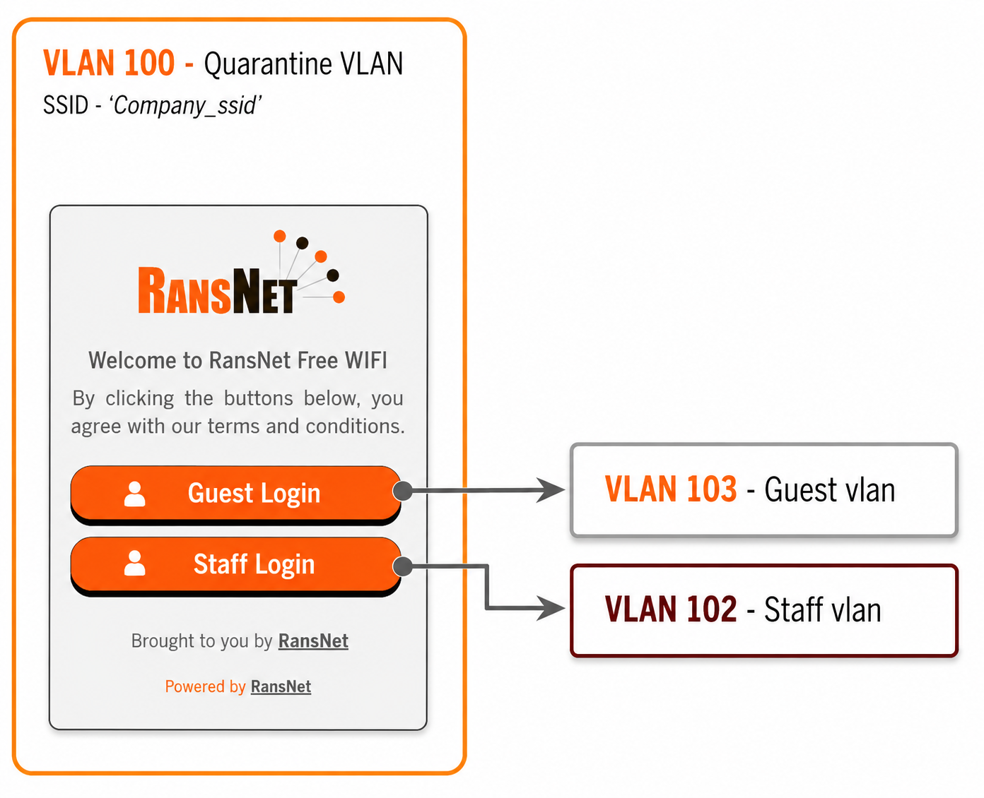
Follow the video guide to create and customize your captive portal. The portal is the login page presented to users on the quarantine VLAN before they are authenticated and moved to their assigned VLAN.
Sample Portal Login Page:
Step 4: Configure Access Profiles on HSG
Access Profiles define VLAN assignment, bandwidth limits, and session timeouts for each user type. These are applied when users authenticate.
GUI Configuration
Navigate to Hotspot Users → Access Profile and create profiles for Quarantine, Staff, and Guest users.
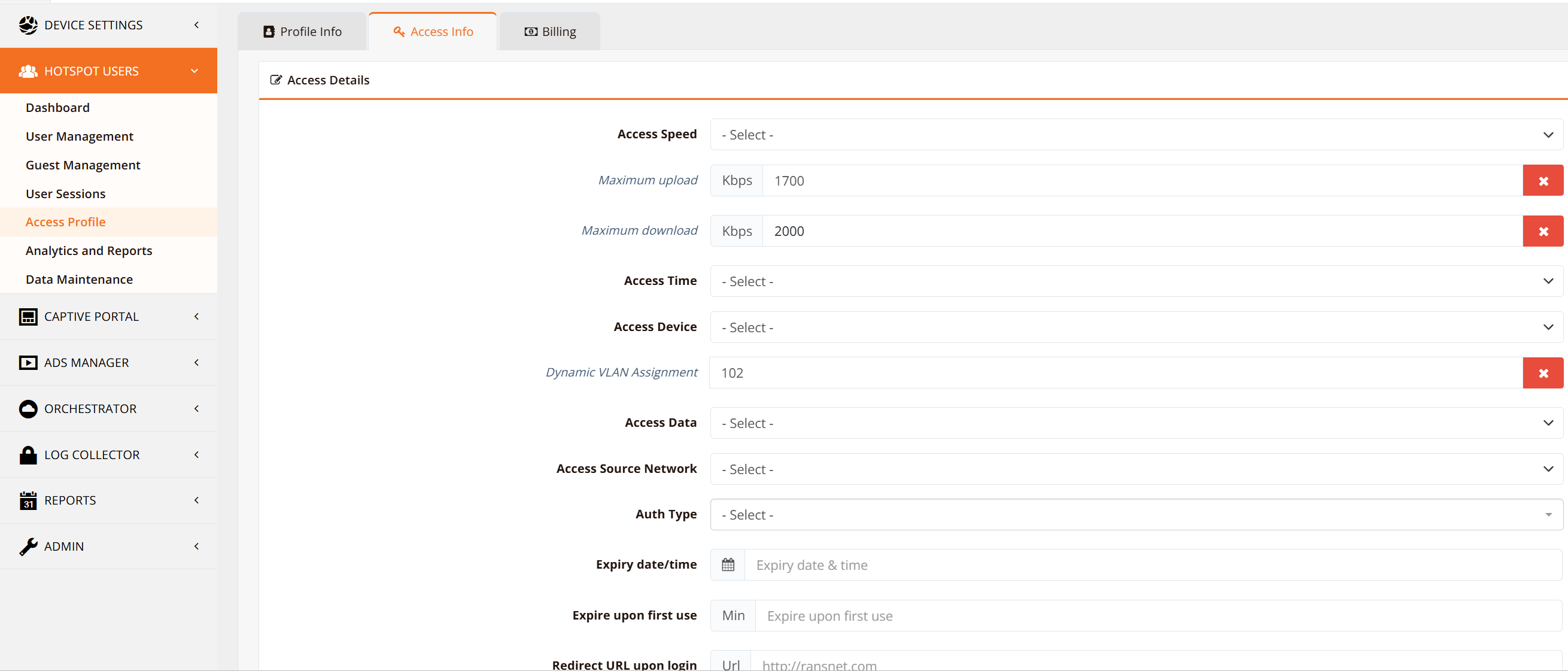
| Profile Name | Associated VLAN | Session Timeout | Idle Timeout | Bandwidth (Upload/Download) | VLAN Assignment |
|---|---|---|---|---|---|
NACDEFAULT |
VLAN 100 | 60 min | 100 min | Unlimited | No reassignment (quarantine) |
Staff_Vlan102 |
VLAN 102 | Unlimited | Unlimited | 1700 Kbps / 2000 Kbps | VLAN 102 (staff) |
Guest_Vlan103 |
VLAN 103 | 1440 min (24 hours) | 30 min | 2000 Kbps / 2000 Kbps | VLAN 103 (guest) |
Tip
Guest profiles can be auto-created by the system when you use self-registration method (Email OTP, SMS OTP, etc.). The auto-generated profile name follows the pattern: RansNet_[DeviceName]_[InterfaceName]_[MAC-last-4]_[MethodName]. You can then edit the auto-generated profile to adjust VLAN assignment and bandwidth limits.
Step 5: Configure Hotspot Instance (VLAN100)
The hotspot instance runs only on the quarantine VLAN to present the login portal. Authenticated users are moved to other VLANs and bypass the hotspot instance entirely.
GUI Configuration
Navigate to Hotspot Settings → Hotspot Instances and click on vlan100 under the Interface column heading.
Hotspot Instance Base Config:
| Field | Value | Description |
|---|---|---|
| Hotspot Enable | Yes |
Enable hotspot portal on this VLAN |
| Hotspot Portal URL | http://captive.ransnet.com/pid/[YourPortalID]/login.php |
Portal login page (use the portal name created in step #3) |
Hotspot Instance Optional Config:
| Field | Value | Description |
|---|---|---|
| Permit External Client Network | 172.16.100.0 |
Quarantine subnet |
| Permit External Client Netmask | 255.255.255.0 |
Allow quarantine clients |
| Redirect/Success URL | http://www.ransnet.com |
Page shown after successful login |
| Intercept DNS Requests | Yes |
Redirect DNS to captive portal (optional) |
CLI Configuration
!
security hotspot vlan100
 hotspot-server 172.16.100.1 ports 5205 4029
 client-network 172.16.100.0 255.255.255.0
 client-static 172.16.100.0 255.255.255.0
 client-local-dns on
 redirect-url http://www.ransnet.com
 radius-server splash.ransnet.com testing123
 hotspot-portal https://captive.ransnet.com/[YourPortalID]/login.php
 hotspot-nac NACDEFAULT
 start
!
Step 6: Configure Wireless AP/WLC to integrate with HSG
The Wireless AP/WLC must be configured as a RADIUS client on the HSG and vice versa.
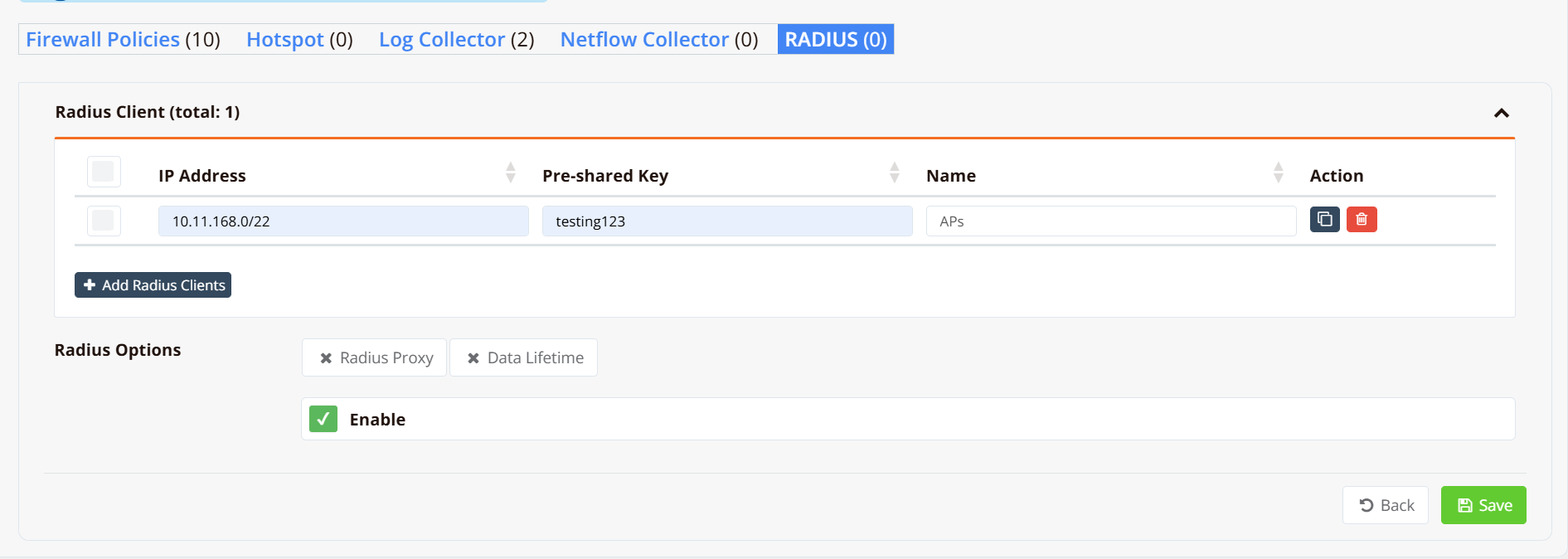
On HSG GUI:
Navigate to Device Settings → Security → RADIUS and add the AP/WLC as a RADIUS client:
- Client IP or Network — IP address or subnet of the AP/WLC (use a network range to include all APs in the management network)
- Pre-shared Key — Shared secret used for RADIUS authentication (must match the AP/WLC RADIUS server configuration)
On AP/WLC:
Configure the SSID with the following settings:
- Enable MAC Authentication (not 802.1x)
- Set RADIUS server to HSG IP
192.168.8.1port1812 - Configure the same Pre-shared Key as defined on HSG
- Enable VLAN Support to honor RADIUS VSA attributes
For detailed steps on configuring a specific AP/WLC vendor, refer to the Extreme Networks AP guide or your AP/WLC vendor documentation. The general workflow is similar across vendors; only the GUI navigation and field names differ.
Verification
| Items to Test | Command | Expected Outcome |
|---|---|---|
| VLAN interfaces UP | show interface vlan |
All three VLANs (100, 102, 103) show UP status with correct IP addresses |
| DHCP server running | show ip dhcp-server |
DHCP servers running on all three VLANs |
| RADIUS server active | show security radius-server |
RADIUS server listening on UDP port 1812 |
| Hotspot instance running | show security hotspot |
vlan100 hotspot shows start status |
| Device associates to SSID | Connect wireless client | Device receives IP from VLAN 100 (quarantine subnet 172.16.100.x) |
| Captive portal appears | Open browser after connect | Login portal page loads automatically (DNS interception) |
| Staff authentication | Login with staff account | Device moves to VLAN 102; receives IP from 172.16.102.x; can ping 172.16.102.1 |
| Guest authentication | Register as guest via SMS OTP | Device moves to VLAN 103; receives IP from 172.16.103.x; can access internet |
| VLAN isolation | From VLAN 102, ping VLAN 103 device | Ping fails (VLANs isolated by default) |
Troubleshooting
| Symptom | Likely Cause | Solution |
|---|---|---|
| Device doesn't get DHCP IP in VLAN 100 | VLAN 100 DHCP server not running; quarantine interface down | Run show ip dhcp-server to confirm enabled. Check tcpdump interface vlan100 port 67 details for DHCP packets. Ensure eth1 is connected to switch. |
| Captive portal doesn't appear | DNS interception disabled; AP not configured for RADIUS; no default route | Enable DNS interception in Hotspot Instance settings. Verify AP RADIUS server points to 192.168.8.1 port 1812. Confirm HSG has default route to ISP. |
| Authentication succeeds but device stays in VLAN 100 | AP doesn't support RADIUS VSA for VLAN assignment; access profile not configured; shared secret mismatch | Verify AP firmware supports VLAN assignment via RADIUS VSA. Check access profile exists in Hotspot Users settings. Confirm shared secret testing123 matches AP RADIUS config. |
| Device moves to VLAN but gets no IP | DHCP server not running on target VLAN; AP sends wrong VLAN ID | Run show ip dhcp-server for target VLAN; enable if needed. Verify RADIUS VSA response contains correct VLAN ID in HSG logs. |
| Device in VLAN 102/103 can't reach Internet | No default route configured for authorized VLAN; firewall blocking outbound | Add default route to ISP for authorized VLAN or upstream firewall. Verify firewall rules permit outbound traffic from authorized VLANs. |
| High CPU on HSG with many authorized users | Hotspot instance processing traffic from authorized VLANs | Confirm access profiles assign users to VLAN 102/103 (not VLAN 100). Verify hotspot service runs only on VLAN 100, not on 102/103. Move authorized VLANs to separate physical interface if possible. |
Best Practices
Performance Optimization
- Dedicated hotspot VLAN — Run hotspot service only on VLAN 100 (quarantine). Authorized VLANs bypass HSG entirely and route at wire speed.
- Session timeouts — Set reasonable session and idle timeouts to prevent stale sessions from consuming HSG memory (staff: unlimited or 24 hours; guests: 24 hours maximum).
- Bandwidth limits — Apply per-profile bandwidth limits (e.g., 2 Mbps for guests, unlimited for staff) rather than per-device limits to reduce CPU overhead.
- VLAN routing — Route authorized VLANs directly through upstream firewalls when possible; avoid backhauling all traffic through HSG.
Security
- Change default shared secret — Replace
testing123with a strong passphrase on both HSG and AP before production. - Disable hotspot on authorized VLANs — Only enable hotspot portal on quarantine VLAN 100; disable on 102/103 to prevent portal re-prompts.
- Restrict inter-VLAN communication — By default, VLANs cannot communicate. If you need authorized VLANs to reach specific destinations (corporate servers, shared printers), add explicit firewall rules or VLAN interfaces to a common uplink device.
- Audit authentication logs — Monitor HSG logs for failed authentication attempts and unusual access patterns.
Related Features
- Hotspot Gateway — Complete HSG configuration and features guide
- Captive Portal — Portal customization, authentication methods, and login options
- VLAN Interfaces — Detailed VLAN configuration on routers
- RADIUS Server — RADIUS authentication configuration and attributes
- Firewall Policies — Inter-VLAN traffic control and access policies