Wi-Fi as WAN
RansNet routers support two Wi-Fi operating modes: AP mode, where the device acts as a wireless access point serving wireless clients, and STA (Station) mode, also known as Wi-Fi as WAN. In STA mode, the device connects to an existing upstream Wi-Fi network as a wireless client, using that connection as a WAN uplink — in the same role as a wired Ethernet or cellular interface.
Wi-Fi as WAN is suited for deployments where a wired broadband connection is unavailable or not yet provisioned — for example, connecting to a building's shared Wi-Fi, using a mobile hotspot as a temporary backhaul, or bridging connectivity across a site during installation.
For AP mode configuration, see Wi-Fi Access Point.
Radio Interfaces
RansNet branch devices expose two Wi-Fi radio interfaces:
| Interface | Radio Band | Typical Use |
|---|---|---|
ath0 |
2.4 GHz | Longer range; better wall penetration; suitable when the upstream AP is further away |
ath1 |
5 GHz | Higher throughput; less interference; preferred where signal quality is good |
In STA mode, the selected radio interface (ath0 or ath1) becomes the WAN-facing wireless client interface and can be configured with IP addressing, route metrics, and link tracking — just like any other WAN interface type.
GUI Configuration
Navigate to Device Settings → Network → Wi-Fi.
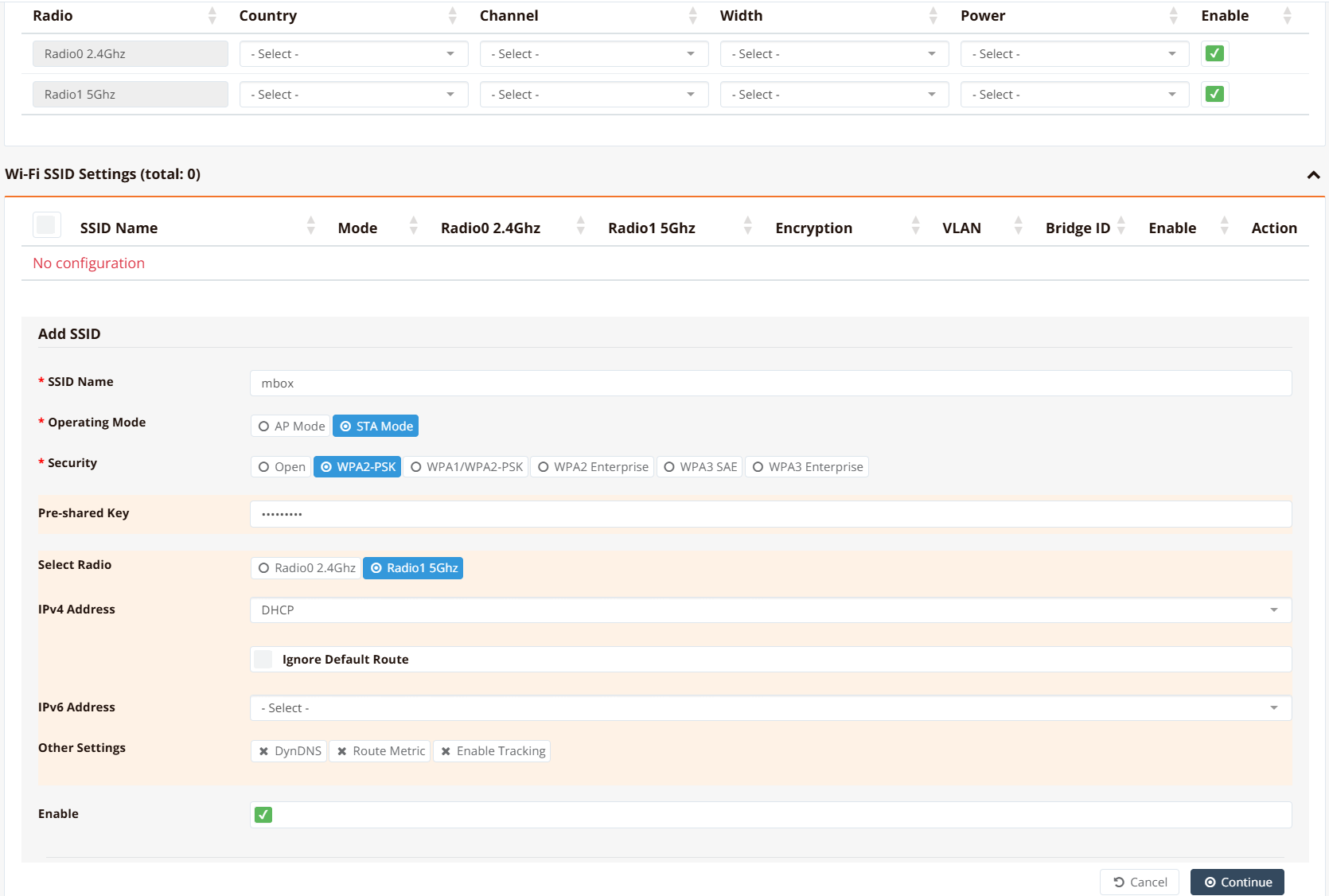
Under Operating Mode, select STA Mode. This switches the radio from access point mode to wireless client (station) mode.
Configure the connection to the upstream Wi-Fi network:
| Field | Description |
|---|---|
| SSID | The network name of the upstream Wi-Fi network to connect to |
| Security / Encryption | Encryption method used by the upstream AP (e.g., WPA2-PSK) |
| Pre-Shared Key (PSK) | The Wi-Fi passphrase for the upstream network |
| IP Address | Set to DHCP to receive an address from the upstream router, or Static to assign a fixed IP |
Note
The SSID and PSK must exactly match the upstream AP's configuration, including case sensitivity. A mismatch will prevent association.
Once STA mode is active, the resulting ath0 or ath1 interface is available as a WAN interface. Navigate to Device Settings → Network → Interfaces to configure IP addressing, route metric, and link tracking for this interface, alongside any other WAN uplinks.
Tip
To use Wi-Fi as WAN as a secondary or failover uplink, assign it a higher Route Metric than the primary WAN interface. Multi-WAN will automatically route traffic via Wi-Fi if the primary link fails.
CLI Configuration
Connect to a 5 GHz upstream network (DHCP)
interface ath1
  ip address dhcp
  enable
!
interface wifi 1
  ssid HomeBroadband
    encryption WPA2-PSK key Letmein99
    client station
    enable
Key points:
interface ath1configures the 5 GHz radio interface; useath0for 2.4 GHzinterface wifi 1references the same radio by index —wifi 0for 2.4 GHz,wifi 1for 5 GHzclient stationsets the radio to STA (client) modeencryption WPA2-PSK key <passphrase>sets the Wi-Fi authentication credentials- Replace
ip address dhcpwith a static address if the upstream network requires a fixed IP
Connect to a 2.4 GHz network with a static IP
interface ath0
  ip address 192.168.1.50/24
  enable
!
interface wifi 0
  ssid OfficeWifi
    encryption WPA2-PSK key MySecretKey
    client station
    enable
!
ip default-gateway 192.168.1.1
Verification
Example output:
================================================================================
  Interface : ath1
================================================================================

  Network Information
  ----------------------------------------
  Admin State            : UP
  Link State             : UP
  MTU                    : 1500 bytes
  IPv4 Address           : 192.168.1.100/24

  Wi-Fi Station
  ----------------------------------------
  SSID                   : HomeBroadband
  Signal                 : -55 dBm (good)
  TX Rate                : 433 Mbps

  Physical Information
  ----------------------------------------
  Link Detected          : yes

================================================================================
Confirm that Link State is UP and the SSID matches the upstream network. A signal level of -70 dBm or better is recommended for stable WAN operation.
Wi-Fi as Backup to 5G
Use Case
5G networks offer significant benefits for industrial automation, autonomous vehicles, and modern AR/VR applications. However, 5G coverage in indoor environments remains inconsistent, while Wi-Fi is widely available and reliable indoors. This creates a common scenario where a device relies on 5G for primary backhaul, but needs a fallback to Wi-Fi when 5G signal is unavailable or degraded.
Using Wi-Fi as WAN as a backup to 5G provides two advantages:
- Indoor coverage — Wi-Fi bridges the gap when 5G signal is poor indoors
- Provider resilience — Wi-Fi typically connects to a different network provider than cellular, reducing the risk of correlated outages
Architecture
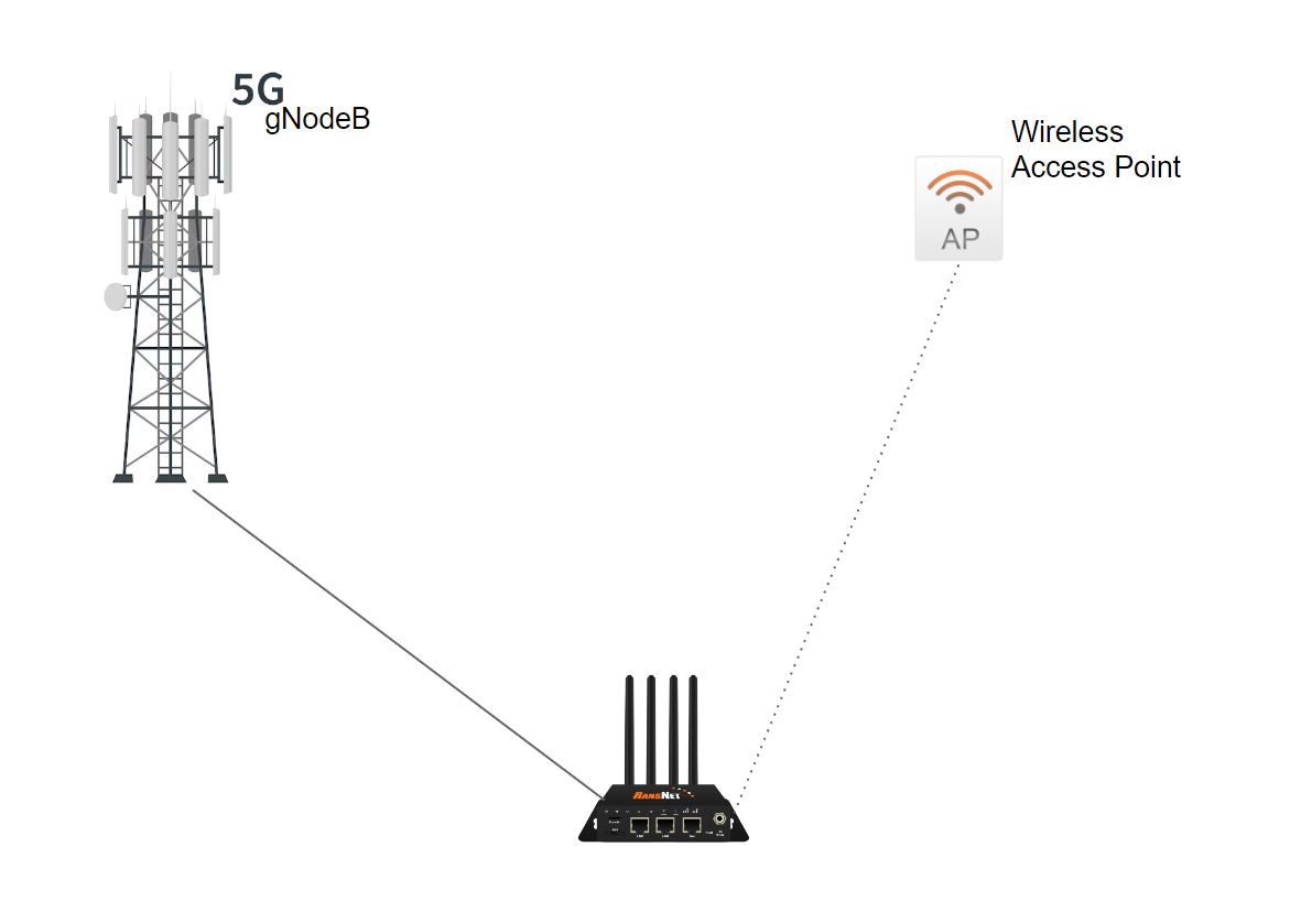
The device maintains two independent WAN links:
- Primary: 5G (wwan0) with route metric 10 (preferred)
- Backup: Wi-Fi (ath0) with route metric 20 (secondary)
The router automatically shifts traffic to Wi-Fi when 5G link becomes unavailable or unreachable. For more advanced failover scenarios, see WAN Failover Configuration.
Configuration Example
interface ath0
  enable
  route-metric 20
  ip address dhcp
!
interface wwan0
  enable
  route-metric 10
  apn providerapn
  nr-mode NR5G
!
interface wifi 0
  country SG
  ssid mbox_wifiaswan
    encryption WPA1/WPA2-PSK key Letmein99
    client station
    enable
Key settings:
route-metric 10on wwan0 — 5G is preferred (lowest metric = highest priority)route-metric 20on ath0 — Wi-Fi is secondary (higher metric = lower priority)ip address dhcp— Both interfaces request IP from their respective upstream networks
Verification
Verify both links are active and metrics are correctly set:
Expected output:
K>* 0.0.0.0/0 [20/0] via 192.168.1.1, ath0, weight 1, 00:05:12
K>* 0.0.0.0/0 [10/0] via 100.67.24.1, wwan0, weight 1, 00:02:34
The 5G default route (wwan0) has metric 10 (selected as primary), and the Wi-Fi default route (ath0) has metric 20 (backup). When 5G fails, the kernel automatically activates the Wi-Fi route.
Inbound Access and Transparent Failover
When 5G and Wi-Fi failover occurs, the device's public IP address may change (each WAN link has a different ISP-assigned IP). If you have inbound access (e.g., through port forwarding), clients connecting to the old IP will lose connectivity.
To provide seamless failover for inbound access, overlay an SD-WAN VPN tunnel on top of both WAN links. Applications then route through the VPN overlay (stable endpoint) rather than directly through the WAN underlay. The router handles failover transparently: the VPN tunnel remains up, only the underlying WAN path changes. From the application's perspective, there is no failover — the connection is uninterrupted.
See Dual-Hub SD-WAN for a complete example of multi-WAN with VPN overlay resilience.