Switch Ports
RansNet SD-Branch routers have multiple GE or FE ports, each configurable as a WAN or LAN interface. Understanding the port architecture of your device is important before configuring them.
- Gateway series (CMG/HSG) and UA-800 — each port is a routed (Layer 3) port, operating independently with its own IP address, like a traditional router interface.
- 520 series (UA-520/HSA-520) — the WAN port (
eth0) is a routed port;LAN1–LAN4are switchports on an internal Layer 2 switch chip, witheth1as the logical uplink between the switch chip and the CPU.
For routed port configuration, refer to Ethernet Interface and VLAN Interface. This page covers switchport configuration for the 520 series.
Hardware Architecture
The 520 series uses an internal Layer 2 switch chip. LAN1–LAN4 are physical switchports on the chip; eth1 is the logical uplink from the chip to the CPU routing engine. All inter-VLAN routing, VPN, firewall, and WAN traffic passes through eth1 via VLAN sub-interfaces — the switch chip handles per-port VLAN tagging and untagging in hardware.
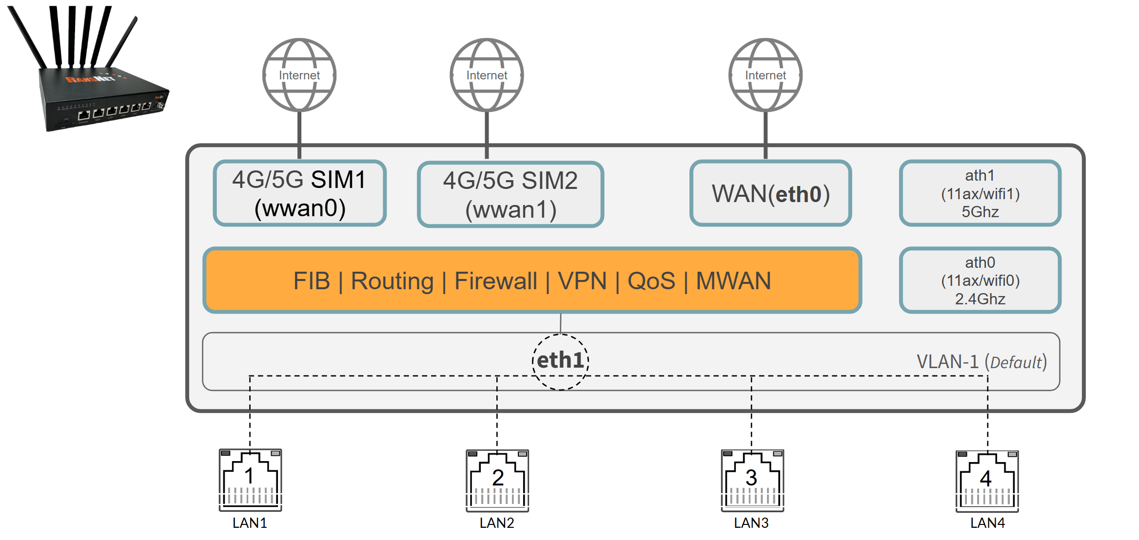
By default, all four LAN ports belong to VLAN 1, tagged to eth1. Connected devices share a single Layer 2 broadcast domain and are served by the router's default LAN gateway on the vlan1 interface.
Configure Access Port
An access port (IEEE 802.1Q untagged port) carries traffic for a single VLAN. The switch chip automatically tags incoming frames with the configured VLAN ID and strips the tag on egress — connected end devices such as PCs, printers, and access points operate normally with no VLAN awareness required.
Note
Create the target VLAN interface on eth1 before assigning a switchport to it. Refer to VLAN Interface for details.
GUI Configuration
Navigate to Device Settings → Network → Switchport. Click the Edit button (pencil icon) for the target port.
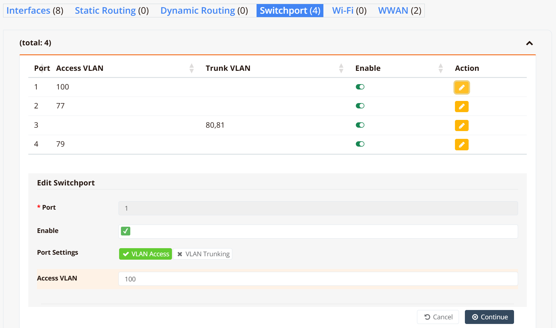
The Edit Switchport panel opens at the bottom of the page:
| Field | Description |
|---|---|
| Port | Physical port number (read-only) |
| Enable | Toggle to enable or disable this switchport |
| Port Settings | Select VLAN Access for a single-VLAN untagged port |
| Access VLAN | The VLAN ID to assign to this port |
Click Continue to save.
Tip
The example above configures LAN1 as an access port on VLAN 100 — for instance, connecting to an upstream ISP modem with DHCP. The VLAN ID here is locally significant only, just use a unique VLAN and configure VLAN interface a "WAN" interface.
CLI Configuration
interface vlan 1 100
 description "Used as WAN, over LAN1"
 enable
 ip address dhcp
!
interface switchport 1
 vlan access 100
!
Repeat for each additional port as needed.
Configure Trunk Port
A trunk port (IEEE 802.1Q tagged port) carries traffic for multiple VLANs simultaneously over a single link. Use this when connecting to a downstream managed switch or a multi-SSID wireless AP where each VLAN must remain logically segregated end-to-end. The downstream device must be configured in trunk mode with matching VLAN IDs.
Note
VLAN 1 is always passed as the native (untagged) VLAN on trunk ports. Ensure the downstream switch port is configured to match.
GUI Configuration
Navigate to Device Settings → Network → Switchport. Click the Edit button for the target port.
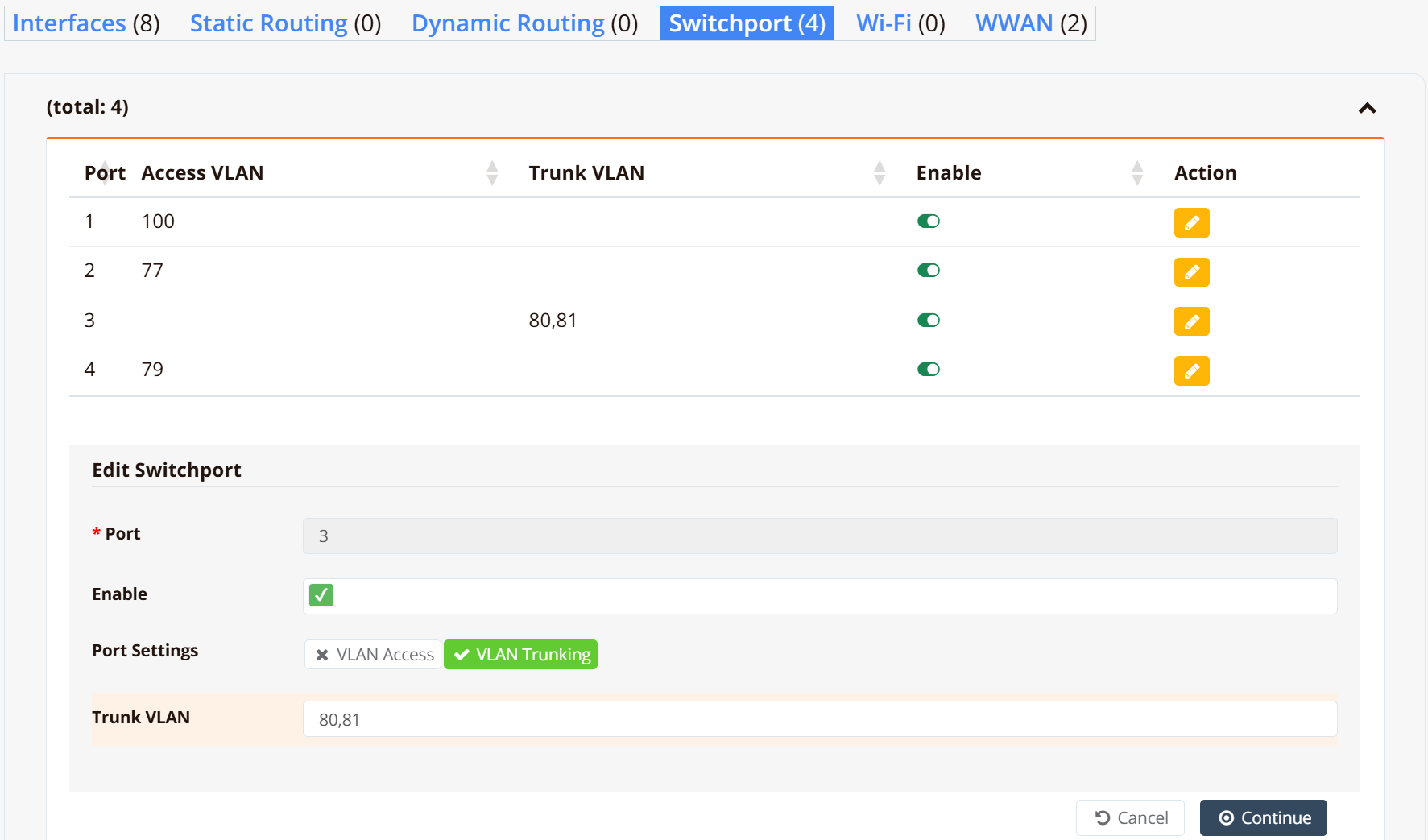
In the Edit Switchport panel:
| Field | Description |
|---|---|
| Port Settings | Select VLAN Trunking |
| Trunk VLAN | Comma-separated list of VLAN IDs to carry as 802.1Q tagged traffic (e.g. 80,81) |
Click Continue to save.
CLI Configuration
First, define the VLAN interfaces on eth1:
interface vlan 1 80
 description VLAN_80
 enable
 ip address 192.168.80.1/24
 dhcp-server
  lease-time 86400 86400
  router 192.168.80.1
  dns 8.8.8.8 8.8.4.4
  range 192.168.80.11 192.168.80.250
  enable
!
interface vlan 1 81
 description VLAN_81
 enable
 ip address 192.168.81.1/24
 dhcp-server
  lease-time 86400 86400
  router 192.168.81.1
  dns 8.8.8.8 8.8.4.4
  range 192.168.81.11 192.168.81.250
  enable
!
Then assign the trunk VLANs to the switchport:
Verification
Example output:
Switch     Port    VLAN            Status  Link                            RX           TX
---------  ------  --------------  ------  ------------------------------  -----------  -----------
switch1    LAN1    100             down    -                               -            -
switch1    LAN2    77              UP      100M/Full [tx/rx]               39.2M        259.4M
switch1    LAN3    1 80(T) 81(T)   UP      1000M/Full [tx/rx]              71.5M        1.1G
switch1    LAN4    79              down    -                               -            -
Key points:
- A single VLAN ID with no suffix (e.g.
100,77) indicates an access port assigned to that VLAN. - Multiple entries where tagged VLANs are suffixed with
(T)(e.g.80(T) 81(T)) indicate a trunk port; VLAN1with no suffix is the native untagged VLAN passed through by default. - Status reflects the operating state; Link reflects the physical link state and negotiated speed/duplex.