Dual-Hub SD-WAN
Dual-hub SD-WAN provides resilience against both underlay (Internet) and overlay (VPN) failures. A branch router maintains dual WAN connections (primary and backup) to two geographically separated hub sites. If the primary WAN link fails, VPN tunnels automatically shift to the backup link. If the primary hub becomes unreachable, traffic automatically routes through the backup hub, ensuring uninterrupted connectivity to the data center.
Overview
How It Works
Dual-hub SD-WAN architecture combines two resilience mechanisms:
- Dual WAN (underlay) — The branch router has two Internet connections to choose from
- Dual VPN (overlay) — The branch router maintains two separate VPN tunnels, one to each hub site
During normal operation, traffic prefers the primary path: primary WAN link + primary VPN tunnel to DC-1. When either the primary WAN or primary hub fails, the router automatically shifts to alternate paths without dropping application traffic.
Note
The DC-1/DC-2 Internet can be any ISP (typically direct from DC hosting provider), as long as they are reachable by router connected to both ISP1 and ISP2. In somes case, the hubs are inter-connected through a private connection, and running VRRP on the LAN side to serve the same group of servers/apps; in some cases, the backup hub is a DR, replicating the same LAN servers and addressesing (usually there's also a private connection for server replication).

Use Cases
| Sector | Scenario | Benefit |
|---|---|---|
| Enterprise | Multi-location offices with redundant HQ connectivity | Continuous access to centralized services even during ISP outages |
| Financial Services | Branch banking centers requiring zero downtime | Automatic failover with no manual intervention or traffic loss |
| Retail | Multi-store chain with DC backup | Point-of-sale systems remain connected during primary link failure |
| Healthcare | Remote clinic with critical patient data access | Instant backup routing to secondary medical records data center |
| Manufacturing | Factory floor with dual-hub ERP access | Production lines continue without interruption during hub/ISP failure |
Requirements
Infrastructure
- Primary Hub (DC-1): RansNet gateway running SD-WAN with direct Internet access and static public IP
- Backup Hub (DC-2): RansNet gateway running SD-WAN with direct Internet access and unique static public IP
- Branch Router: RansNet Branch router with dual WAN interfaces (Broadband, LTE, 5G, PPPoE, or mixed)
- NNI Between ISP: Both ISPs must have network-to-network interconnections to both hubs, so the branch router can reach either hub public IP via any available path. For example, traffic can route through Primary WAN → ISP1 → ISP2 → DC-2, or Backup WAN → ISP2 → ISP1 → DC-1.
Network Configuration
- Common hub LAN networks — Both hubs must advertise the same internal networks
- Unique hub IPs — Each hub gateway has its own public IP address for IPsec termination
- Branch site identity — Branch network must be unique and advertised to both hubs
Network Planning
| Site | Network | Gateway | Role |
|---|---|---|---|
| Primary Hub (DC-1) | vlan10: 192.168.10.0/24 | 192.168.10.1 | Datacenter networks |
| Primary Hub (DC-1) | vlan20: 192.168.20.0/24 | 192.168.20.1 | Datacenter networks |
| Backup Hub (DC-2) | vlan10: 192.168.10.0/24 | 192.168.10.1 | Datacenter networks |
| Backup Hub (DC-2) | vlan20: 192.168.20.0/24 | 192.168.20.1 | Datacenter networks |
| Branch-A | vlan10: 192.168.11.0/24 | 192.168.11.1 | Branch LAN |
| Branch-A | vlan20: 192.168.21.0/24 | 192.168.21.1 | Branch LAN |
| Branch-B | vlan10: 192.168.12.0/24 | 192.168.12.1 | Branch LAN |
| Branch-B | vlan20: 192.168.22.0/24 | 192.168.22.1 | Branch LAN |
Network Behavior
Steady-State (Normal Operation)
When both WAN links and both hub gateways are healthy:
- Branch router maintains two live default routes (one per ISP)
- Router automatically elects primary WAN link (typically the first to come up or lowest metric, eg. primary fiber, backup 5G)
- Both VPN tunnels are established via primary WAN link but traffic prefers the primary tunnel:
- Primary VPN tunnel (to DC-1) is active
- Backup VPN tunnel (to DC-2) remains standby
- All application traffic flows to DC-1
Tip
The branch router always uses the lowest metric default route to build VPN tunnels. When the primary WAN link is available, both VPN tunnels use the primary path. When the primary WAN link fails, both tunnels automatically shift to the backup WAN link (the only available default route).

Failover Scenario 1: Primary WAN Link Fails
When the branch's primary Internet connection drops:
- Primary WAN link becomes unavailable
- Both VPN tunnels automatically shift to the backup WAN Link-2
- Application traffic continues through primary VPN tunnel (to DC-1), now overlaid on backup WAN link
- Failover time is typically 2–5 seconds (depending on link detection timer)
- When primary WAN recovers, both tunnels shift back to primary link

Failover Scenario 2: Primary Hub (DC-1) Unreachable
When DC-1 gateway becomes unreachable (link down, gateway outage, or upstream routing failure):
- Primary VPN tunnel to DC-1 fails (no response to keepalive probes)
- BGP route via primary VPN tunnel is withdrawn. Route via backup tunnel is active.
- Application traffic automatically routes through backup VPN tunnel to DC-2
- Users connect to the same corporate network resources now via DC-2
- When DC-1 recovers, traffic shifts back to primary tunnel

Deployment
Architecture Principles
Before configuring, understand these core concepts:
| Concept | Description |
|---|---|
| Spoke-to-Spoke (L3) | Branch router learns routes from both hubs and makes forwarding decisions based on BGP weight and cost. Requires BGP enabled on all devices. |
| BGP Weight | Routes with higher weight are preferred. Primary tunnel uses weight 100; backup uses weight 0 (or lower). |
| Overlay Independence | The VPN overlay (which hub you reach) is independent from the underlay (which ISP you use). |
| Transparent Failover | Applications don't detect failover because the VPN tunnels remain up; only the active path changes. |
Configuration Steps
Step 1: Configure Basic Network Settings and WAN Failover
Navigate to Device Settings → Network → Interfaces and configure interfaces for both gateway and branch routers. For basic network setting configuration, see Network Configuration.
For branch routers, configure automatic failover between the branch's two WAN links so that the VPN tunnel can seamlessly shift paths. See WAN Failover Configuration for detailed setup.
Key requirement: Use Option 2 (PBR with Tracking) to detect upstream failures, not just physical link down. This ensures the VPN tunnel shifts paths if the primary ISP link fails at the network level (not just at the physical port).
Step 2: Configure Hub Gateway VPN Instance
Configure a unique VPN instance on each hub gateway
- Advertise common DC networks in both instances
- Set different higher BGP weights on primary hub: primary = 100, backup = 0 (default)
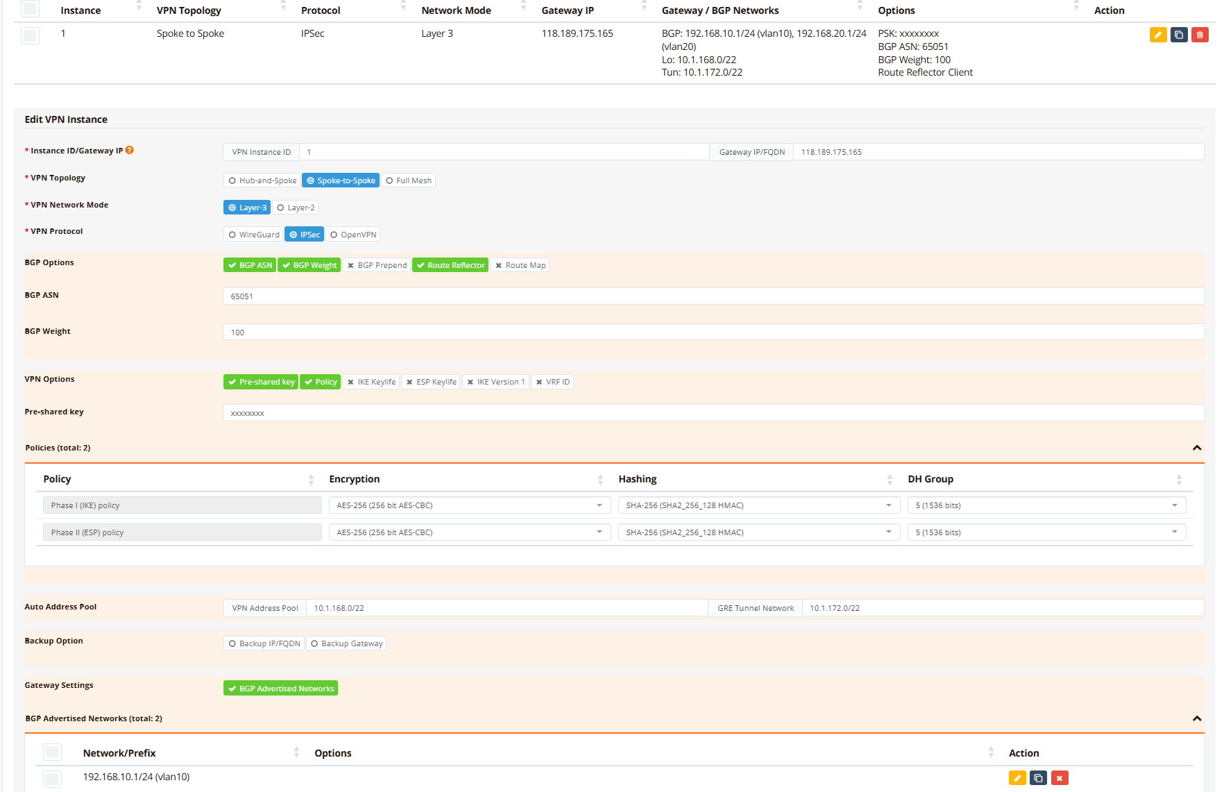
On the hub gateway device, navigate to Device Settings → SD-WAN → VPN, then click Add VPN Instance.
Define VPN topology and protocol settings:
- Topology: Spoke-to-Spoke (L3) or Hub-and-Spoke, depending on whether branches communicate directly with each other
- Protocol: IPsec or WireGuard (IPsec recommended for maximum interoperability)
- Advertised Networks: All hub datacenter networks (vlan10: 192.168.10.0/24, vlan20: 192.168.20.0/24)
Primary hub (DC-1) VPN Setting
Backup hub (DC-2) VPN Setting
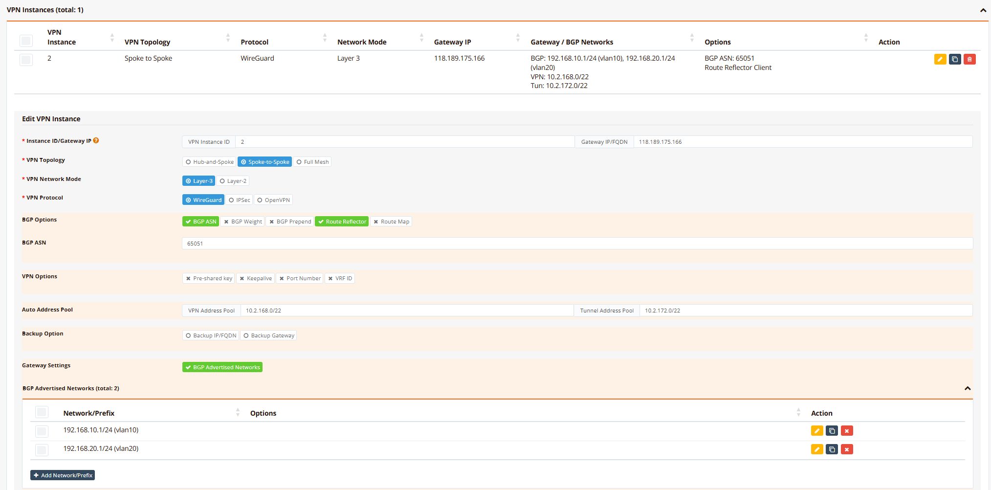
Info
For demonstration purposes, the backup hub uses WireGuard protocol while the primary hub uses IPsec. Both protocols are fully supported on both hubs; you may use IPsec for both hubs if preferred.
Step 3: Enroll Branch Routers into VPN Instance
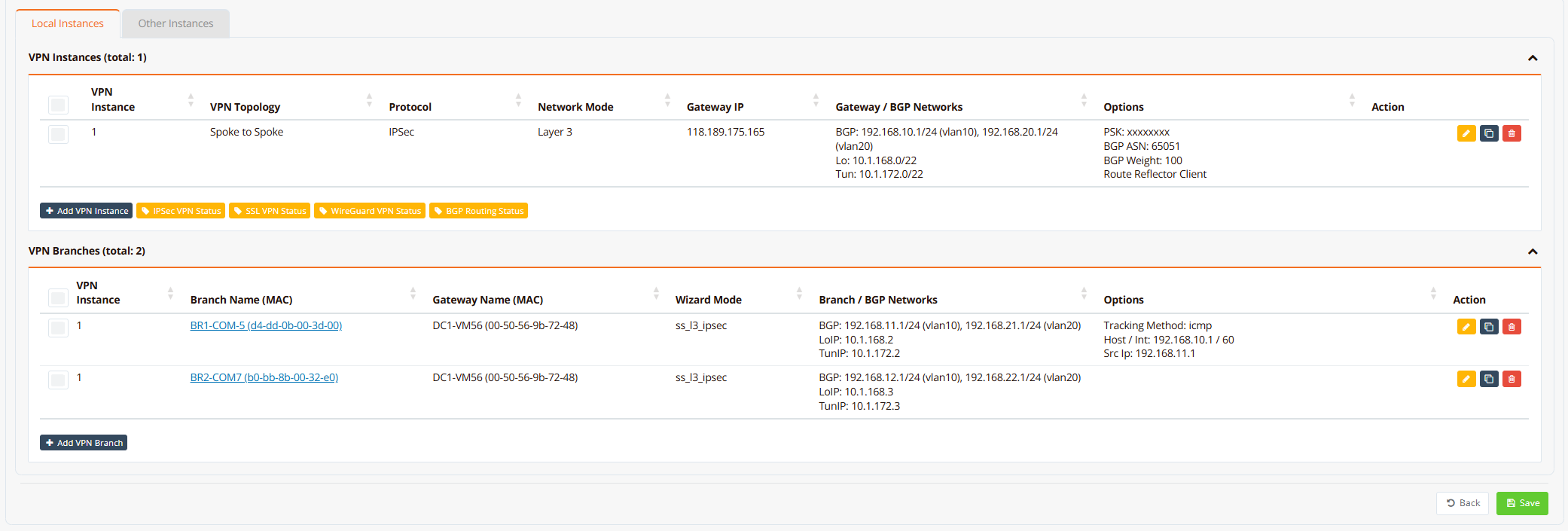
On the hub gateway device, navigate to Device Settings → SD-WAN → VPN, scroll down to VPN Branches section.
Click Add VPN Branch and configure each branch:
- Select VPN instance and branch: From the dropdown list, select the pre-configured VPN instance, then select target branch router (branch name). Join both VPN instances (one for each hub).
- Advertised Networks: All branch LAN networks (e.g., vlan10: 192.168.11.0/24, vlan20: 192.168.21.0/24)
Branch router enrollment on hub/DC-1
Branch router enrollment on hub/DC-2
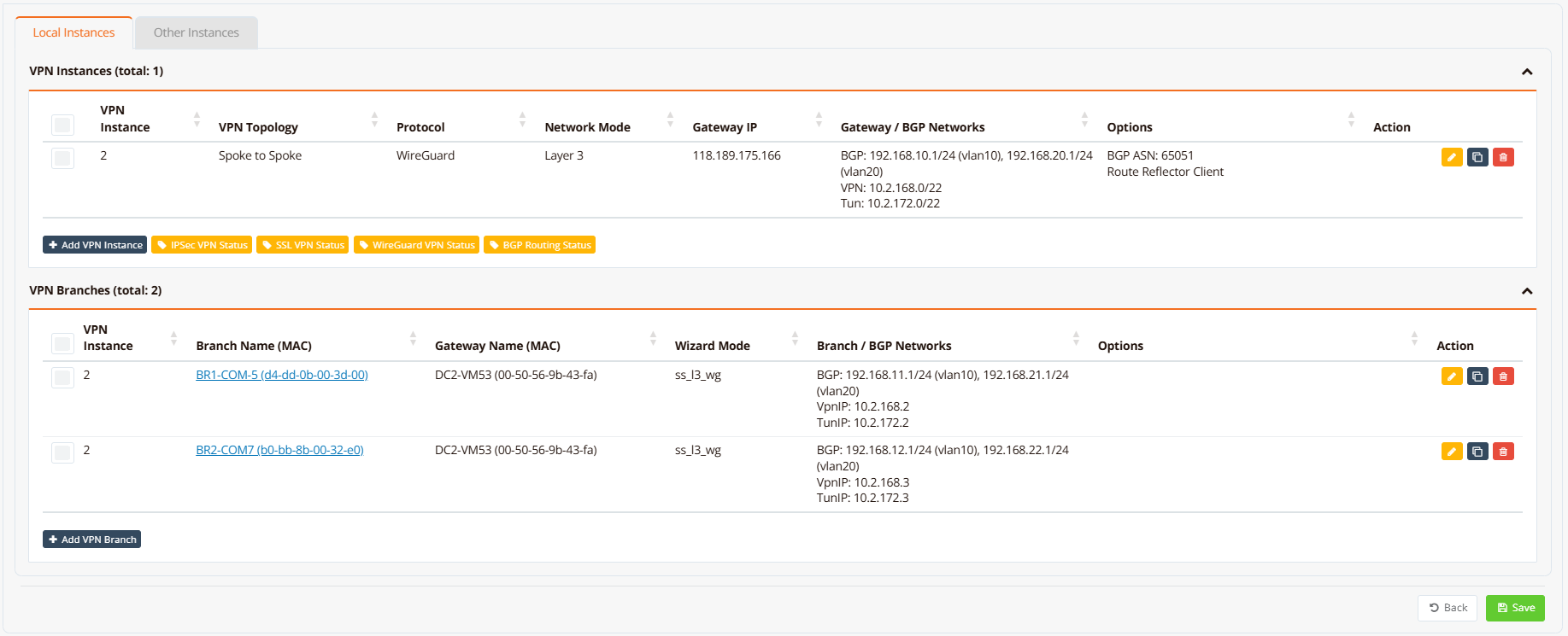
Optionally enable tunnel tracking to monitor tunnel health and auto-reset if the tunnel becomes stuck or corrupted.
Step 4: Configure Firewall Access Rules
Navigate to Device Settings → Security → Firewall and configure firewall-access rules to permit traffic between sites based on your security policies.
For detailed firewall configuration, see Firewall Access Policies.
Tip
To quickly test this deployment in a lab or development environment, download pre-configured GUI backups: DC-1, DC-2, BR-1, BR-2. Import each backup into the corresponding device, update the WAN IP addresses to match your environment, and run Resync Config. See Export and Import GUI Config for detailed import instructions.
Verification
Use these commands to verify dual-WAN SD-WAN configuration and diagnose issues:
| What to Check | Command | Expected Output |
|---|---|---|
| Active WAN links | show interface eth0 and show interface wwan0 |
Both eth0 and wwan0 show UP with IP addresses assigned |
| Primary WAN selection | show ip route include 0.0.0.0 |
Two default routes visible; primary route (lower metric) selected as active |
| VPN tunnel status | show ipsec status |
Tunnel shows ESTABLISHED with active keepalive |
| Branch BGP adjacency | show ip bgp summary |
Neighbor shows UP with received prefixes |
| Learned branch routes | show ip bgp and show ip route bgp |
All branch networks present with BGP metric 200 |
| Connectivity to branch | ping <branch-gateway> |
Ping succeeds with round-trip latency ~5-10 ms (varies with distance) |
Example output on primary hub/DC-1:
DC1-VM56# show ip interface
Interface    IP_Address       NetMask          Broadcast        MAC_Address
----------------------------------------------------------------------------------------------
lo           127.0.0.1        255.0.0.0        0.0.0.0          N/A
eth0         10.65.31.56      255.255.255.0    10.65.31.255     00:50:56:9b:72:48
vlan10       192.168.10.1     255.255.255.0    192.168.10.255   00:50:56:9b:72:48
vlan20       192.168.20.1     255.255.255.0    192.168.20.255   00:50:56:9b:72:48
vxlan1       10.1.172.1       255.255.252.0    10.1.175.255     76:7a:f0:30:39:43
DC1-VM56#
DC1-VM56# show ipsec status
================================================================================
 IPSec Status
 Uptime  : 9 hours, since Jun 07 14:35:12 2026
 Local   : 10.65.31.56
 Peers   : 2 established, 0 connecting
================================================================================

Peer                                State          Local Net         Remote Net             Tx       Rx  Uptime      IKE(Auth)    ESP
------------------------------------------------------------------------------------------------------------------------------------------------
b0-bb-8b-00-32-e0 (111.65.56.76)    ESTABLISHED    10.1.168.1/32     10.1.168.3/32       1.2MB    1.2MB  8 hours     IKEv2(PSK)   AES-256/SHA256
d4-dd-0b-00-3d-00 (61.13.198.166)   ESTABLISHED    10.1.168.1/32     10.1.168.2/32      43.4KB   54.1KB  20 minutes  IKEv2(PSK)   AES-256/SHA256

DC1-VM56# show interface vxlan1
================================================================================
  Interface : vxlan1
================================================================================

  Network Information
  ----------------------------------------
  Admin State            : UP
  Link State             : UP
  MAC Address            : 76:7a:f0:30:39:43
  MTU                    : 1500 bytes
  IPv4 Address           : 10.1.172.1/22
  IPv4 Broadcast         : 10.1.175.255
  IPv6 Address           : fe80::747a:f0ff:fe30:3943/64 [link]

  VXLAN Peers
  ----------------------------------------
66:f8:63:f1:33:bf dst 10.1.168.2 self
e6:cf:7a:ab:c3:e1 dst 10.1.168.3 self

  Physical Information
  ----------------------------------------
  Speed                  : Unknown!
  Duplex                 : Unknown! (255)
  Port Type              : Other
  Auto-Negotiation       : off
  Link Detected          : yes

================================================================================
DC1-VM56#

DC1-VM56# show ip bgp summary

IPv4 Unicast Summary (VRF default):
BGP router identifier 10.65.31.56, local AS number 65051 vrf-id 0
BGP table version 26
RIB entries 11, using 2112 bytes of memory
Peers 2, using 1448 KiB of memory
Peer groups 1, using 64 bytes of memory

Neighbor        V         AS   MsgRcvd   MsgSent   TblVer  InQ OutQ  Up/Down State/PfxRcd   PfxSnt Desc
*10.1.172.2     4      65051       642       647        0    0    0 00:52:22            2        6 N/A
*10.1.172.3     4      65051      6219      6233        0    0    0 08:37:03            2        6 N/A

Total number of neighbors 2
* - dynamic neighbor
2 dynamic neighbor(s), limit 2000
DC1-VM56# show ip bgp

Instance default:
BGP table version is 26, local router ID is 10.65.31.56, vrf id 0
Default local pref 100, local AS 65051
Status codes:  s suppressed, d damped, h history, * valid, > best, = multipath,
               i internal, r RIB-failure, S Stale, R Removed
Nexthop codes: @NNN nexthop's vrf id, < announce-nh-self
Origin codes:  i - IGP, e - EGP, ? - incomplete
RPKI validation codes: V valid, I invalid, N Not found

   Network          Next Hop            Metric LocPrf Weight Path
*> 192.168.10.0/24  0.0.0.0                  0         32768 i
*>i192.168.11.0/24  10.1.172.2               0    100    100 i
*>i192.168.12.0/24  10.1.172.3               0    100    100 i
*> 192.168.20.0/24  0.0.0.0                  0         32768 i
*>i192.168.21.0/24  10.1.172.2               0    100    100 i
*>i192.168.22.0/24  10.1.172.3               0    100    100 i

Displayed  6 routes and 6 total paths
DC1-VM56# show ip route bgp
Codes: K - kernel route, C - connected, S - static, R - RIP,
       O - OSPF, I - IS-IS, B - BGP, E - EIGRP, N - NHRP,
       T - Table, v - VNC, V - VNC-Direct, A - Babel, F - PBR,
       f - OpenFabric,
       > - selected route, * - FIB route, q - queued, r - rejected, b - backup
       t - trapped, o - offload failure

B>* 192.168.11.0/24 [200/0] via 10.1.172.2, vxlan1, weight 1, 00:20:12
B>* 192.168.12.0/24 [200/0] via 10.1.172.3, vxlan1, weight 1, 00:20:12
B>* 192.168.21.0/24 [200/0] via 10.1.172.2, vxlan1, weight 1, 00:20:12
B>* 192.168.22.0/24 [200/0] via 10.1.172.3, vxlan1, weight 1, 00:20:12
DC1-VM56# ping 192.168.11.1 source 192.168.10.1
PING 192.168.11.1 (192.168.11.1) from 192.168.10.1 : 56(84) bytes of data.
64 bytes from 192.168.11.1: icmp_seq=1 ttl=64 time=7.11 ms
64 bytes from 192.168.11.1: icmp_seq=2 ttl=64 time=5.99 ms
64 bytes from 192.168.11.1: icmp_seq=3 ttl=64 time=4.44 ms
64 bytes from 192.168.11.1: icmp_seq=4 ttl=64 time=4.86 ms
64 bytes from 192.168.11.1: icmp_seq=5 ttl=64 time=4.40 ms

--- 192.168.11.1 ping statistics ---
5 packets transmitted, 5 received, 0% packet loss, time 4006ms
rtt min/avg/max/mdev = 4.398/5.358/7.109/1.046 ms
DC1-VM56#
Example output on secondary hub/DC-2:
DC2-VM53# show ip interface
Interface    IP_Address       NetMask          Broadcast        MAC_Address
----------------------------------------------------------------------------------------------
lo           127.0.0.1        255.0.0.0        0.0.0.0          N/A
eth0         10.65.31.53      255.255.255.0    10.65.31.255     00:50:56:9b:43:fa
vlan10       192.168.10.1     255.255.255.0    192.168.10.255   00:50:56:9b:43:fa
vlan20       192.168.20.1     255.255.255.0    192.168.20.255   00:50:56:9b:43:fa
wg2          10.2.168.1       255.255.255.255  10.2.168.1       N/A
vxlan2       10.2.172.1       255.255.252.0    10.2.175.255     16:9c:b4:1b:a2:2f
DC2-VM53#
DC2-VM53# show wg
interface: wg2
  public key: dHzHRvbF4Z8FXL3wTj4P5YPaiwuKKeVQghu37uZUHlw=
  private key: (hidden)
  listening port: 51822

WG Peer                 PublicKey                                     PublicIP:Port           Peer Net         Download/Upload        LastUpdate
---------------------------------------------------------------------------------------------------------------------------
2-b0-bb-8b-00-32-e0     fkUEcx2ixkB4fDxiYC3c4kcEqpjB8vfXAHINWCWWan0=  111.65.71.8:43311       10.2.168.3/32    23.02 KiB/21.50 KiB    5 seconds ago
2-d4-dd-0b-00-3d-00     RruzcjHy9ncIV9/Jvk5krU5GOqA2NiYXPpYgBBiEj2w=  61.13.198.166:51822     10.2.168.2/32    14.28 KiB/22.62 KiB    19 seconds ago
Total configured WG peers:      2
Total active WG peers:          2
Total malfunction WG peers:     0
Total inactive WG peers:        0
DC2-VM53#
DC2-VM53# show interface vxlan2
================================================================================
  Interface : vxlan2
================================================================================

  Network Information
  ----------------------------------------
  Admin State            : UP
  Link State             : UP
  MAC Address            : 16:9c:b4:1b:a2:2f
  MTU                    : 1500 bytes
  IPv4 Address           : 10.2.172.1/22
  IPv4 Broadcast         : 10.2.175.255
  IPv6 Address           : fe80::149c:b4ff:fe1b:a22f/64 [link]

  VXLAN Peers
  ----------------------------------------
fa:4f:3a:10:f2:53 dst 10.2.168.3 self
6a:47:48:24:64:32 dst 10.2.168.2 self

  Physical Information
  ----------------------------------------
  Speed                  : Unknown!
  Duplex                 : Unknown! (255)
  Port Type              : Other
  Auto-Negotiation       : off
  Link Detected          : yes

================================================================================
DC2-VM53# show ip bgp summary

IPv4 Unicast Summary (VRF default):
BGP router identifier 10.65.31.53, local AS number 65051 vrf-id 0
BGP table version 6
RIB entries 11, using 2112 bytes of memory
Peers 2, using 1448 KiB of memory
Peer groups 1, using 64 bytes of memory

Neighbor        V         AS   MsgRcvd   MsgSent   TblVer  InQ OutQ  Up/Down State/PfxRcd   PfxSnt Desc
*10.2.172.2     4      65051        81        83        0    0    0 00:06:26            2        6 N/A
*10.2.172.3     4      65051        80        82        0    0    0 00:06:22            2        6 N/A

Total number of neighbors 2
* - dynamic neighbor
2 dynamic neighbor(s), limit 2000
DC2-VM53#
DC2-VM53# show ip bgp

Instance default:
BGP table version is 6, local router ID is 10.65.31.53, vrf id 0
Default local pref 100, local AS 65051
Status codes:  s suppressed, d damped, h history, * valid, > best, = multipath,
               i internal, r RIB-failure, S Stale, R Removed
Nexthop codes: @NNN nexthop's vrf id, < announce-nh-self
Origin codes:  i - IGP, e - EGP, ? - incomplete
RPKI validation codes: V valid, I invalid, N Not found

   Network          Next Hop            Metric LocPrf Weight Path
*> 192.168.10.0/24  0.0.0.0                  0         32768 i
*>i192.168.11.0/24  10.2.172.2               0    100      0 i
*>i192.168.12.0/24  10.2.172.3               0    100      0 i
*> 192.168.20.0/24  0.0.0.0                  0         32768 i
*>i192.168.21.0/24  10.2.172.2               0    100      0 i
*>i192.168.22.0/24  10.2.172.3               0    100      0 i

Displayed  6 routes and 6 total paths
DC2-VM53#
DC2-VM53# show ip route bgp
Codes: K - kernel route, C - connected, S - static, R - RIP,
       O - OSPF, I - IS-IS, B - BGP, E - EIGRP, N - NHRP,
       T - Table, v - VNC, V - VNC-Direct, A - Babel, F - PBR,
       f - OpenFabric,
       > - selected route, * - FIB route, q - queued, r - rejected, b - backup
       t - trapped, o - offload failure

B>* 192.168.11.0/24 [200/0] via 10.2.172.2, vxlan2, weight 1, 00:06:43
B>* 192.168.12.0/24 [200/0] via 10.2.172.3, vxlan2, weight 1, 00:06:39
B>* 192.168.21.0/24 [200/0] via 10.2.172.2, vxlan2, weight 1, 00:06:43
B>* 192.168.22.0/24 [200/0] via 10.2.172.3, vxlan2, weight 1, 00:06:39
DC2-VM53#
DC2-VM53# ping 192.168.11.1 source 192.168.10.1
PING 192.168.11.1 (192.168.11.1) from 192.168.10.1 : 56(84) bytes of data.

--- 192.168.11.1 ping statistics ---
5 packets transmitted, 0 received, 100% packet loss, time 4091ms

DC2-VM53#
Note
DC-2 can't ping to branch network while DC-1 is UP (because return will route back to DC-1 instead).
Example output on branch router:
BR1-COM5# show ip interface
Interface    IP_Address       NetMask          Broadcast        MAC_Address
----------------------------------------------------------------------------------------------
lo           127.0.0.1        255.0.0.0        0.0.0.0          N/A
eth0         10.18.18.212     255.255.255.0    10.18.18.255     d4:dd:0b:00:3d:00
vlan1        192.168.8.1      255.255.252.0    192.168.11.255   76:05:9c:93:b5:fd
vlan10       192.168.11.1     255.255.255.0    192.168.11.255   76:05:9c:93:b5:fd
vlan20       192.168.21.1     255.255.255.0    192.168.21.255   76:05:9c:93:b5:fd
vxlan1       10.1.172.2       255.255.252.0    10.1.175.255     66:f8:63:f1:33:bf
wwan0        10.92.252.20     0.0.0.0          10.92.252.20     N/A
wg2          10.2.168.2       255.255.255.255  10.2.168.2       N/A
vxlan2       10.2.172.2       255.255.252.0    10.2.175.255     6a:47:48:24:64:32
BR1-COM5#
BR1-COM5# show ipsec status
================================================================================
 IPSec Status
 Uptime  : 27 minutes, since Jun 07 15:34:39 2026
 Local   : 10.18.18.212
 Peers   : 1 established, 0 connecting
================================================================================

Peer                                State          Local Net         Remote Net             Tx       Rx  Uptime      IKE(Auth)    ESP
------------------------------------------------------------------------------------------------------------------------------------------------
118.189.175.165 (118.189.175.165)   ESTABLISHED    10.1.168.2/32     10.1.168.1/32      75.5KB   63.5KB  27 minutes  IKEv2(PSK)   AES-256/SHA256

BR1-COM5# show wg
-----------------------
Default WG Instance:
-----------------------
interface: wg2
  public key: RruzcjHy9ncIV9/Jvk5krU5GOqA2NiYXPpYgBBiEj2w=
  private key: (hidden)
  listening port: 51822

WG Peer                 PublicKey                                     PublicIP:Port           Peer Net         Download/Upload        LastUpdate
---------------------------------------------------------------------------------------------------------------------------
2-00-50-56-9b-43-fa     dHzHRvbF4Z8FXL3wTj4P5YPaiwuKKeVQghu37uZUHlw=  118.189.175.166:51822   10.2.168.1/32    25.83 KiB/20.75 KiB    1 minute, 52 seconds ago
Total configured WG peers:      1
Total active WG peers:          1
Total malfunction WG peers:     0
Total inactive WG peers:        0
BR1-COM5# show interface vxlan1
================================================================================
  Interface : vxlan1
================================================================================

  Network Information
  ----------------------------------------
  Admin State            : UP
  Link State             : UP
  MAC Address            : 66:f8:63:f1:33:bf
  MTU                    : 1500 bytes
  IPv4 Address           : 10.1.172.2/22
  IPv4 Broadcast         : 10.1.175.255
  IPv6 Address           : fe80::64f8:63ff:fef1:33bf/64 [link]

  VXLAN Peers
  ----------------------------------------
00:00:00:00:00:00 dst 10.1.168.1 self permanent
76:7a:f0:30:39:43 dst 10.1.168.1 self

  Physical Information
  ----------------------------------------
  Link Detected          : yes

================================================================================
BR1-COM5# show interface vxlan2
================================================================================
  Interface : vxlan2
================================================================================

  Network Information
  ----------------------------------------
  Admin State            : UP
  Link State             : UP
  MAC Address            : 6a:47:48:24:64:32
  MTU                    : 1500 bytes
  IPv4 Address           : 10.2.172.2/22
  IPv4 Broadcast         : 10.2.175.255
  IPv6 Address           : fe80::6847:48ff:fe24:6432/64 [link]

  VXLAN Peers
  ----------------------------------------
00:00:00:00:00:00 dst 10.2.168.1 self permanent
16:9c:b4:1b:a2:2f dst 10.2.168.1 self

  Physical Information
  ----------------------------------------
  Link Detected          : yes

================================================================================
BR1-COM5# show ip bgp summary

IPv4 Unicast Summary (VRF default):
BGP router identifier 10.18.18.212, local AS number 65051 vrf-id 0
BGP table version 38
RIB entries 11, using 1496 bytes of memory
Peers 2, using 1425 KiB of memory
Peer groups 2, using 64 bytes of memory

Neighbor        V         AS   MsgRcvd   MsgSent   TblVer  InQ OutQ  Up/Down State/PfxRcd   PfxSnt Desc
10.1.172.1      4      65051      6715      6713        0    0    0 00:59:57            4        2 N/A
10.2.172.1      4      65051       126       124        0    0    0 00:10:01            4        2 N/A

Total number of neighbors 2
BR1-COM5# show ip bgp

Instance default:
BGP table version is 38, local router ID is 10.18.18.212, vrf id 0
Default local pref 100, local AS 65051
Status codes:  s suppressed, d damped, h history, * valid, > best, = multipath,
               i internal, r RIB-failure, S Stale, R Removed
Nexthop codes: @NNN nexthop's vrf id, < announce-nh-self
Origin codes:  i - IGP, e - EGP, ? - incomplete
RPKI validation codes: V valid, I invalid, N Not found

   Network          Next Hop            Metric LocPrf Weight Path
* i192.168.10.0/24  10.2.172.1               0    100      0 i
*>i                 10.1.172.1               0    100    100 i
*> 192.168.11.0/24  0.0.0.0                  0         32768 i
* i192.168.12.0/24  10.2.172.1               0    100      0 i
*>i                 10.1.172.1               0    100    100 i
* i192.168.20.0/24  10.2.172.1               0    100      0 i
*>i                 10.1.172.1               0    100    100 i
*> 192.168.21.0/24  0.0.0.0                  0         32768 i
* i192.168.22.0/24  10.2.172.1               0    100      0 i
*>i                 10.1.172.1               0    100    100 i

Displayed  6 routes and 10 total paths
BR1-COM5# show ip route bgp
Codes: K - kernel route, C - connected, S - static, R - RIP,
       O - OSPF, B - BGP, N - NHRP, T - Table, v - VNC,
       V - VNC-Direct,
       > - selected route, * - FIB route, q - queued, r - rejected, b - backup
       t - trapped, o - offload failure

B>* 192.168.10.0/24 [200/0] via 10.1.172.1, vxlan1, weight 1, 00:27:47
B>* 192.168.12.0/24 [200/0] via 10.1.172.1, vxlan1, weight 1, 00:27:47
B>* 192.168.20.0/24 [200/0] via 10.1.172.1, vxlan1, weight 1, 00:27:47
B>* 192.168.22.0/24 [200/0] via 10.1.172.1, vxlan1, weight 1, 00:27:47
BR1-COM5# ping 192.168.10.1 source 192.168.11.1
PING 192.168.10.1 (192.168.10.1) from 192.168.11.1: 56 data bytes
64 bytes from 192.168.10.1: seq=0 ttl=64 time=4.698 ms
64 bytes from 192.168.10.1: seq=1 ttl=64 time=5.130 ms
64 bytes from 192.168.10.1: seq=2 ttl=64 time=4.509 ms
64 bytes from 192.168.10.1: seq=3 ttl=64 time=4.368 ms
64 bytes from 192.168.10.1: seq=4 ttl=64 time=4.864 ms

--- 192.168.10.1 ping statistics ---
5 packets transmitted, 5 packets received, 0% packet loss
round-trip min/avg/max = 4.368/4.713/5.130 ms
BR1-COM5# ping 192.168.12.1 source 192.168.11.1
PING 192.168.12.1 (192.168.12.1) from 192.168.11.1: 56 data bytes
64 bytes from 192.168.12.1: seq=0 ttl=63 time=83.787 ms
64 bytes from 192.168.12.1: seq=1 ttl=63 time=35.470 ms
64 bytes from 192.168.12.1: seq=2 ttl=63 time=82.971 ms
64 bytes from 192.168.12.1: seq=3 ttl=63 time=42.593 ms
64 bytes from 192.168.12.1: seq=4 ttl=63 time=82.241 ms

--- 192.168.12.1 ping statistics ---
5 packets transmitted, 5 packets received, 0% packet loss
round-trip min/avg/max = 35.470/65.412/83.787 ms
BR1-COM5#
Note
Branch learnt both DC routes from BGP, but the DC-1 route has weight of 100 hence it's more preferred.
Alternative: Use Backup Gateway Option
Simplified Hub Redundancy
The Backup Gateway option provides a simpler alternative to the dual-VPN tunnel approach shown above. Instead of maintaining two separate VPN tunnels with BGP route selection, the branch maintains a single VPN tunnel with an automatic fallback peer IP.
When to use:
- Simpler deployments where active/passive failover is sufficient (no load balancing or traffic steering needed)
- Smaller branch networks with fewer VLANs or traffic policies
- When you want minimal configuration on the backup hub
How it works:
- Primary hub (DC-1) runs one VPN instance with the Backup Gateway option enabled
- All VPN settings on the primary hub are automatically replicated to the backup hub (DC-2), but using DC-2's unique public IP
- Branch maintains one VPN tunnel to the primary hub, but also knows the backup hub's IP
- If the primary hub becomes unreachable (tracked via keepalive probes), the branch automatically reconnects to the backup hub
- When the primary hub recovers, traffic shifts back automatically
Configuration
Navigate to the primary gateway's VPN instance settings and configure the Backup Gateway option:
- Go to Device Settings → SD-WAN → VPN
- Select the VPN instance and click Edit
- Under Backup Option, select Backup Gateway
- Enter the backup hub's public IP address
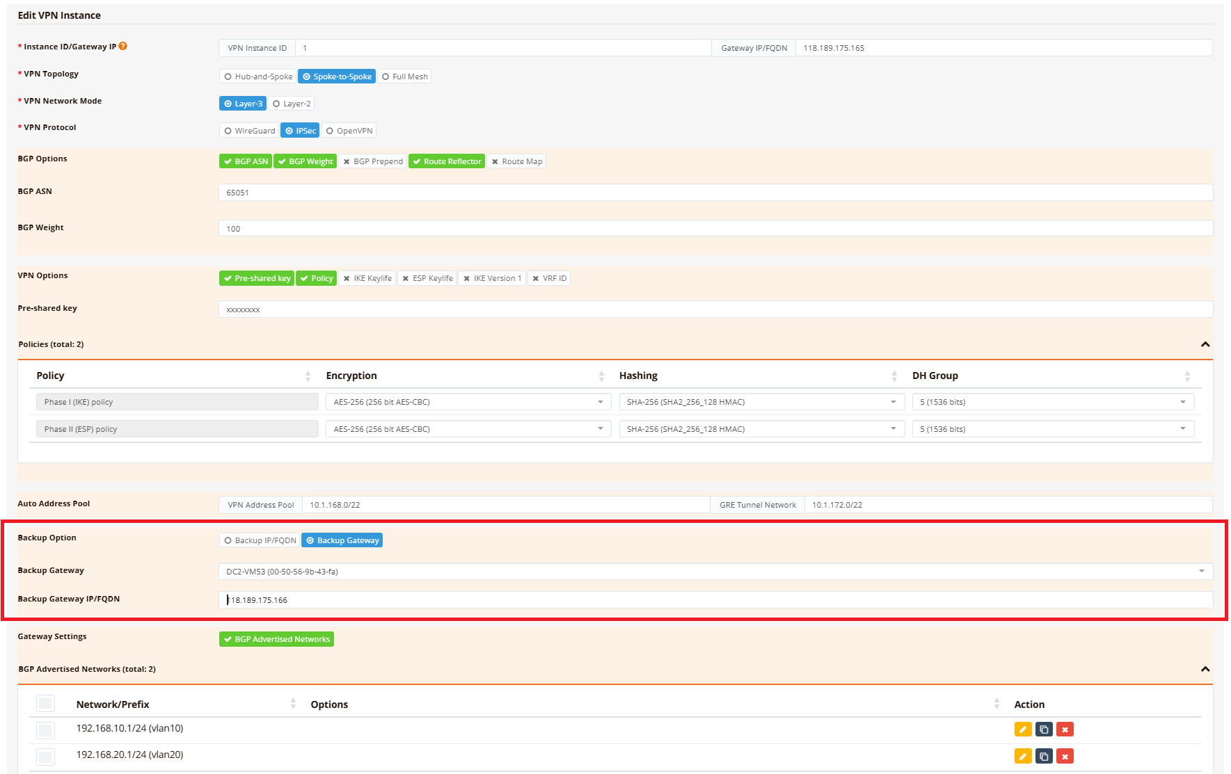
Important:
- Both gateway public IPs must be unique and reachable by all branch devices
- No manual VPN configuration is needed on the backup gateway — all settings are replicated automatically
- Configure the backup hub with the same datacenter networks as the primary hub
Branch Configuration
The branch automatically receives the backup peer IP through the VPN instance enrollment. The resulting IPsec configuration looks like this:
!
ipsec peer 118.189.175.165
  backup-peer 118.189.175.166
  local-id d4-dd-0b-00-3d-00
  local-net 10.1.168.2/32
  remote-net 10.1.168.1/32
  policy ike 1 esp 1
  psk xxxxxxxx
  track icmp 192.168.10.1 60 src 192.168.11.1 log
!
The backup-peer parameter tells the branch to automatically reconnect to the backup hub IP if the primary hub becomes unreachable.
Comparison: Dual-VPN vs Backup Gateway
| Feature | Dual-VPN Tunnels (above) | Backup Gateway (this section) |
|---|---|---|
| Number of VPN tunnels | Two active tunnels | One active tunnel + one backup peer |
| Failover speed | <5 seconds (BGP route withdrawal) | <30 seconds (probing and tunnel re-establishment to backup IP) |
| Traffic steering | Possible (via PBR + firewall marking) | Not supported |
| Load balancing | Possible (traffic split across hubs) | Not possible |
| Complexity | Higher (BGP configuration on all devices) | Lower (automatic replication) |
| Best for | Large networks, traffic engineering, active/active | Smaller networks, simple failover, active/passive |
Troubleshooting
Common Issues
| Symptom | Likely Cause | Solution |
|---|---|---|
| VPN tunnel fails to establish | Hub has firewall blocking IPsec from branch public IP | Verify hub firewall permits UDP 500, UDP 4500 (IPsec), or UDP 51821 (WireGuard) from branch WAN IPs; check NAT rules if hub is behind a router |
| Branch learns hub routes but hub doesn't learn branch routes | Branch networks are not advertised | Check BGP configuration advertises branch networks |
| Primary WAN fails but VPN tunnel doesn't failover to backup WAN | Backup WAN not configured; route metric not set correctly; tracking not detecting failure | Verify backup WAN (wwan0) is UP and has IP assigned; confirm eth0 metric = 10, wwan0 metric = 20 (show ip route); check PBR route (if using upstream tracking, show ip pbr) |
| Intermittent connectivity; tunnel flaps between WAN links | Tracking probe too aggressive; false failovers due to temporary packet loss | Increase tracking probe interval (e.g., timer 15s instead of 5s); change probe target to more reliable host (e.g., 8.8.8.8 instead of ISP gateway) |
| Hub can ping branch but branch cannot ping hub | Return traffic asymmetric; branch firewall blocking inbound ICMP | Verify hub firewall permits ICMP from branch LAN networks; check branch outbound firewall rules allow return traffic |
| Hub is not learning all branch routes | VPN instance not enrolling all branches | Navigate to Hub VPN Instance → VPN Branches; verify all branches are added and configured with correct advertised networks |
Debugging Commands
RansNet# show interface eth0
RansNet# show interface wwan0
RansNet# show ip route
RansNet# show ip route include 0.0.0.0
RansNet# show ipsec status
RansNet# show interface vxlan1
RansNet# show ip bgp summary
RansNet# show ip bgp
RansNet# show ip route bgp
RansNet# show logging system filter track
RansNet# ping <hub-gateway-ip>
Best Practices
Resilience
- Diverse ISPs — Use different ISP providers for primary and backup WAN links to avoid shared dependencies (e.g., fiber + LTE, or different fiber providers)
- Geographic separation — Place backup hub (DC-2) in a different data center or geographic region from primary hub
- Test failover regularly — Simulate failures and verify traffic switches as expected; document failover times
Performance
- Appropriate probing — Use reliable public DNS servers (8.8.8.8, 1.1.1.1) for health probes; avoid probing directly to ISP gateways which may be unreachable from some locations
- WAN link metrics — Explicitly set primary WAN with lower metric than backup to avoid unintended primary/backup flipping
- Monitor tunnel latency — Backup hubs may have higher latency; ensure applications can tolerate variance during failover
Security
- Encryption on all tunnels — Both primary and backup VPN tunnels must use identical encryption policies; mismatched policies prevent backup failover
- Access control — Apply firewalls on both hubs with identical security policies; asymmetric policies cause traffic asymmetry and dropped return packets
- BGP authentication — Use BGP MD5 or other authentication to prevent unauthorized route injection
- Hub route filtering — Apply route-maps on hubs to only advertise intended DC networks; prevents accidental leakage of hub-internal routes