Sample Hotspot Deployment (Multi-SSID / Multi-VLAN)
This case study walks through a typical on-premise Hotspot Gateway (HSG) deployment for a basic hotspot network that broadcasts multiple SSIDs, where each SSID maps to its own VLAN and presents a unique captive portal — delivering a differentiated experience per user group (e.g., staff, guests, cafeteria visitors).
Use Cases
This multi-SSID / multi-VLAN model suits any venue serving distinct user populations from a single gateway:
| Venue | Typical SSIDs |
|---|---|
| Hotels | Staff, Guest Rooms, Conference/Events |
| Shopping malls | Staff, Shoppers, Tenant Stores |
| Tourism & attractions | Staff, Visitors, VIP |
| Airports & stadiums | Staff/Operations, Public, Lounge/Premium |
Architecture Overview
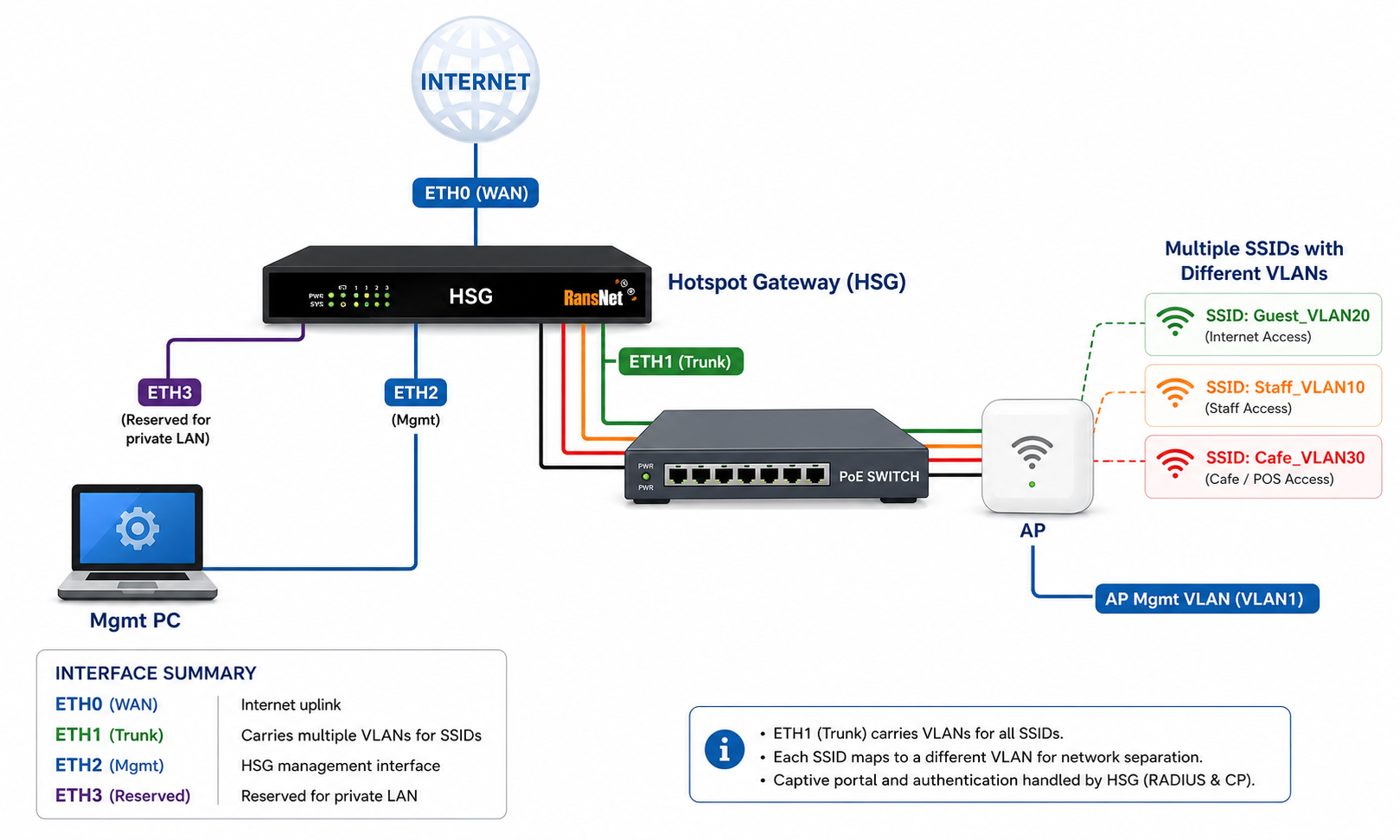
The deployment uses a single HSG as the gateway, DHCP server, RADIUS server, and captive portal controller, with downstream access points broadcasting the SSIDs:
- WAN (eth0) — Connects to the ISP device (ONT/modem); pre-configured to obtain a DHCP IP from upstream.
- LAN (eth1) — Connects to the LAN switch; serves the AP management network
192.168.8.0/22and trunks the user VLANs. - OOB Management (eth2) — Dedicated out-of-band port for administration (
10.10.10.1/24). - Access Points — Any vendor's APs connect to the switch, draw management IPs from VLAN1, and broadcast each SSID tagged to its assigned VLAN (VLAN10, 20, 30).
- Per-VLAN portals — Each VLAN terminates on the HSG with its own hotspot instance, captive portal, and login method.
Key design points:
- Any type of access point can be used on the LAN side.
- A dedicated management VLAN (VLAN1) is used for AP/WLC addressing.
- Each SSID maps to its own VLAN, and each VLAN has its own unique landing page and login experience.
Requirements
| Requirement | Detail |
|---|---|
| HSG firmware | Version 20260608-1700 or later. See Firmware Upgrades. |
| WAN uplink | ISP ONT, modem, or upstream router providing DHCP on the WAN port. |
| LAN switch | VLAN-capable (802.1Q) switch supporting trunk ports. |
| Access points | Any vendor; must support multi-SSID with per-SSID VLAN tagging. |
| Management PC | Connected to the OOB management port (eth2) for initial setup. |
Cabling and Prerequisites
Before configuring the HSG, complete the physical setup:
-
Connect WAN — Connect the HSG WAN port (eth0) to the ISP device (ONT or modem).
Info
The WAN port (eth0) is pre-configured to obtain a DHCP IP from the ISP ONT/modem (or upstream router).
-
Connect LAN — Connect the HSG eth1 port to the LAN switch.
Info
The eth1 port is pre-configured to serve DHCP to the LAN on network
192.168.8.0/22. Access points receive their management IP from this range. IPs192.168.8.2–192.168.8.99are reserved for a WLC or other infrastructure devices. -
Connect access points — Connect the APs to the LAN switch and use the default VLAN1 as the management VLAN for AP/WLC addressing.
-
Configure the switch — Add the user VLANs (VLAN10, 20, 30) on the switch, set all relevant switch ports to trunk mode, and permit all VLANs on each port.
Info
Alternatively, keep the switch on the default VLAN (VLAN1) and let the APs handle VLAN tagging — broadcast the SSIDs from the AP and do not assign VLANs on the switch ports.
-
Configure APs — Configure each AP to broadcast the desired SSID and assign each SSID to its pre-configured VLAN.
-
Connect management PC — Connect a PC to the eth2 port for management.
Info
The eth2 port is pre-configured to serve DHCP for management access (
10.10.10.0/24).
Deployment Steps
Step 1: Access the Hotspot Management UI
From the management PC connected to eth2, browse to https://10.10.10.1 and log in with your administrator credentials.
Step 2 (Optional): Create Entity, User Account, and Permissions
This step is optional for on-premise deployments — complete it only if you need to provide different administrators with different access rights.
Step 3: Create VLANs on the eth1 Interface
Navigate to NETWORK SETTINGS → Interfaces → VLAN and create three VLANs on eth1. Refer to VLAN Interfaces for detailed field descriptions.
| VLAN | Purpose | Gateway IP |
|---|---|---|
| VLAN10 | Staff | 172.16.10.1/24 |
| VLAN20 | Guest | 172.16.20.1/24 |
| VLAN30 | Cafeteria | 172.16.30.1/24 |
Step 4: Create and Configure Captive Portals
Create a separate captive portal for each VLAN, choosing a distinct template per portal to give each SSID its own look and feel. Refer to Captive Portal Configuration.
| Portal Name | Template | Maps to |
|---|---|---|
| Portalvlan10 | Central | VLAN10 (Staff) |
| Portalvlan20 | Prestige | VLAN20 (Guest) |
| Portalvlan30 | Any template | VLAN30 (Cafeteria) |
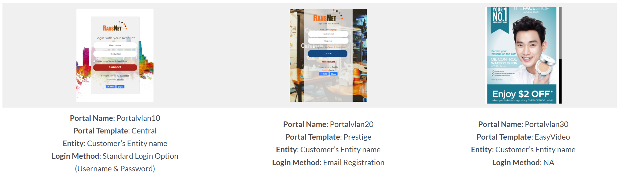
For each portal, configure the Login Method — enable Username/Password and Email OTP as needed. Refer to Login Methods.
Step 5: Configure Hotspot Instances
Navigate to DEVICE SETTINGS → Hotspot. Click Add Hotspot,
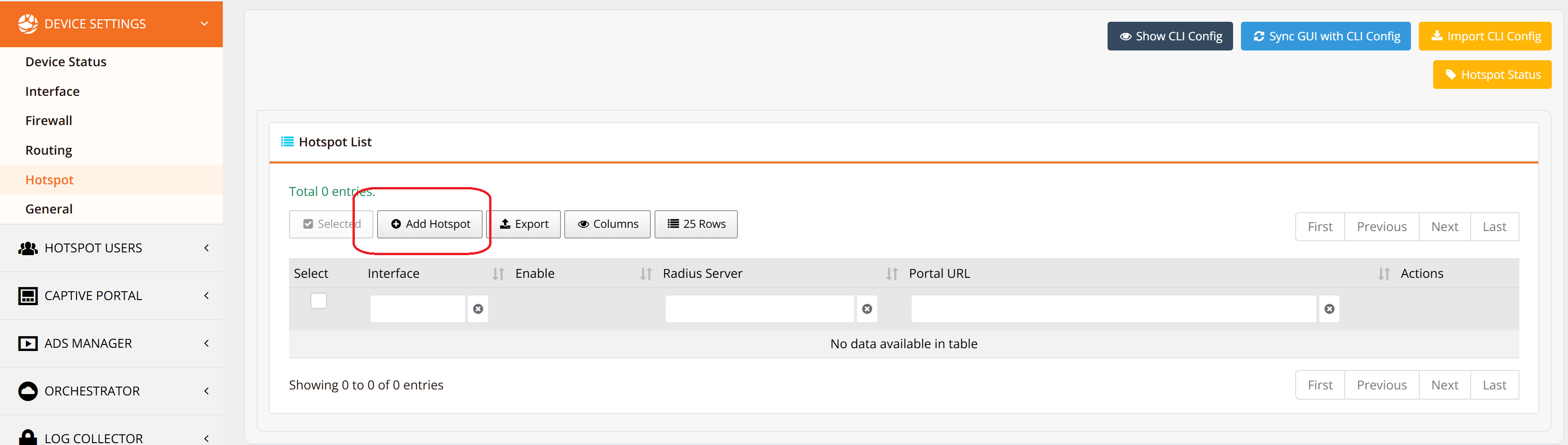
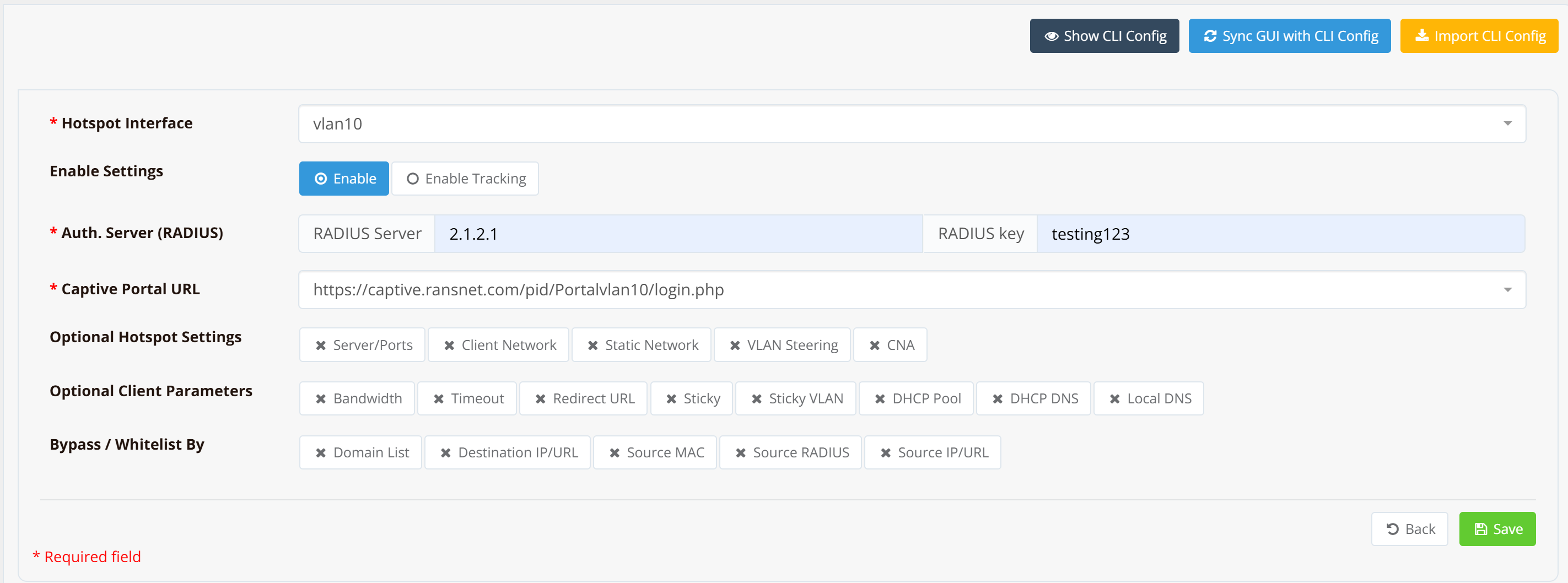
Select each VLAN and complete the settings for each instance.
| Instance | Portal URL |
|---|---|
| vlan10 | https://captive.ransnet.com/pid/Portalvlan10/login.php |
| vlan20 | https://captive.ransnet.com/pid/Portalvlan20/login.php |
| vlan30 | https://captive.ransnet.com/pid/Portalvlan30/login.php |
Step 6: Configure Access Control and Users
Set up the access profiles and user accounts that match each portal's login method.
Staff (VLAN10) — Username/Password:
- Configure a Username/Password access profile for the staff portal (Portalvlan10). Refer to Access Rights and Profiles.
- Create the staff user accounts and assign them to the respective access profile. Refer to User Management.
Guest (VLAN20) — Email Registration:
Configure an Email Registration profile for guest users (Portalvlan20).
Note
The Email Registration profile is auto-created after the first successful Email Registration test on the captive portal. Once tested, the profile appears in Access Profile using the naming format RansNet_[Device Name]_[Interface Name]_[MAC last 4 digits]_emailonepageotp — for example, RansNet_mbox_br-vlan10_96-19_emailonepageotp. Click the profile name to configure its account-info settings to your requirements.
Example CLI Configuration
The following is a complete reference configuration for this deployment. The base network, firewall, and RADIUS settings are shown first, followed by the per-VLAN hotspot instances.
Base Network, Firewall, and Services:
hostname HSG800-WT
!
interface eth0
 description "Default connection to WAN"
 enable
 ip address dhcp
!
interface eth1
 description "Default connection to LAN"
 enable
 ip address 192.168.8.1/22
 dhcp-server
  description "DHCP-ETH1 DHCP"
  lease-time 86400
  router 192.168.8.1
  dns 8.8.8.8 8.8.4.4
  range 192.168.8.100 192.168.11.254
!
interface eth2
 description "Default OOB-Mgmt"
 enable
 ip address 10.10.10.1/24
 dhcp-server
  lease-time 86400 86400
  router 10.10.10.1
  dns 8.8.8.8 8.8.4.4
  range 10.10.10.10 10.10.10.20
  enable
!
interface eth3
 description "Reserved network"
!
interface vlan 1 10
 description "Staff VLAN"
 enable
 ip address 172.16.10.1/24
 dhcp-server
  description "Staff VLAN10 DHCP"
  lease-time 86400
  router 172.16.10.1
  dns 8.8.8.8 8.8.4.4
  range 172.16.10.2 172.16.10.254
  enable
!
interface vlan 1 20
 description "Guest VLAN"
 enable
 ip address 172.16.20.1/24
 dhcp-server
  description "Guest VLAN20 DHCP"
  lease-time 86400
  router 172.16.20.1
  dns 8.8.8.8 8.8.4.4
  range 172.16.20.2 172.16.20.254
  enable
!
interface vlan 1 30
 description "Cafeteria VLAN"
 enable
 ip address 172.16.30.1/24
 dhcp-server
  description "Cafeteria VLAN30 DHCP"
  lease-time 86400
  router 172.16.30.1
  dns 8.8.8.8 8.8.4.4
  range 172.16.30.2 172.16.30.254
  enable
!
interface loopback
 enable
 ip address 2.1.2.1/32
!
ip name-server 8.8.8.8 8.8.4.4
!
ip ntp-server 203.211.159.1 62.201.225.9
!
ip host captive.ransnet.com 2.1.2.1 rewrite
!
firewall-input 10 permit all tcp dport 443 src 10.0.0.0/8 admin remark "WEB mgmt from OOB"
firewall-input 11 permit all tcp dport 22 src 10.0.0.0/8 remark "SSH mgmt from OOB"
!
firewall-access 10 permit outbound eth0
!
firewall-snat 10 overload outbound eth0
!
security radius-server
 client 2.1.2.1 key testing123 name HSG800WT
 start
Hotspot Configuration:
Each hotspot instance uses interface dhcp-server service to assign IP address to clients, so there's no specific dhcp setting required hotspot instance setting.
security hotspot vlan10
 hotspot-server 172.16.10.1 ports 5205 4029
 client-network 172.16.10.0 255.255.255.0
 client-static 172.16.10.0 255.255.255.0
 client-local-dns on
 redirect-url http://www.ransnet.com
 radius-server splash.ransnet.com testing123
 hotspot-portal https://captive.ransnet.com/pid/Portalvlan10/login.php
 start
!
security hotspot vlan20
 hotspot-server 172.16.20.1 ports 5549 4985
 client-network 172.16.20.0 255.255.255.0
 client-static 172.16.20.0 255.255.255.0
 client-local-dns on
 redirect-url http://www.ransnet.com
 radius-server splash.ransnet.com testing123
 hotspot-portal https://captive.ransnet.com/pid/Portalvlan20/login.php
 start
!
security hotspot vlan30
 hotspot-server 172.16.30.1 ports 5780 5408
 client-network 172.16.30.0 255.255.255.0
 client-static 172.16.30.0 255.255.255.0
 client-local-dns on
 redirect-url http://www.ransnet.com
 radius-server splash.ransnet.com testing123
 hotspot-portal https://captive.ransnet.com/pid/Portalvlan30/login.php
 start
Verification
After completing the deployment, verify each layer end-to-end:
| Items to Test | Command / Action | Expected Outcome |
|---|---|---|
| WAN connectivity | show interface eth0 |
Interface shows UP with a valid DHCP IP from the ISP. |
| VLAN interfaces | show interface vlan10 (and 20, 30) |
Each VLAN shows UP with its gateway IP (e.g., 172.16.10.1/24). |
| Hotspot Status | show security hotspot |
Check hotspot service running status |
| AP management IP | Check the AP's admin page | AP has an IP in 192.168.8.100–192.168.11.254. |
| Client gets correct VLAN IP | Connect a device to each SSID | Device receives a DHCP IP from the matching VLAN subnet (e.g., SSID→VLAN20 gives 172.16.20.x). |
| Portal redirect | Open a browser on the connected client | Client is redirected to that VLAN's unique portal page. |
| Login method | Complete login on each portal | Staff authenticates by username/password; guests via Email OTP. |
| Internet access | Browse after authentication | Client reaches the internet through the WAN (SNAT via eth0). |
Troubleshooting
| Symptom | Likely Cause | Solution |
|---|---|---|
| Client connects to SSID but gets no IP | VLAN not trunked to the AP, or DHCP server disabled on the VLAN | Confirm switch port is trunk and permits the VLAN. Run show ip dhcp-server to verify the VLAN DHCP scope is enabled. |
| Client gets IP but no portal appears | Hotspot instance not started, or wrong portal URL | Verify the hotspot instance is started and the hotspot-portal URL matches the created portal. |
| All SSIDs land on the same portal | SSIDs not mapped to distinct VLANs on the AP | Reconfigure the AP so each SSID is tagged to its own VLAN. |
| Email OTP login fails | SMTP not configured | Configure SMTP under Application Settings. |
| Cannot reach management UI | Management PC not on eth2 / OOB firewall rule | Confirm the PC has a 10.10.10.x IP; verify firewall-input rules permit the OOB source. |
Best Practices
- Segment by trust level — Keep staff, guest, and public traffic on separate VLANs with their own DHCP scopes and portals, as shown here.
- Reserve infrastructure IPs — Keep AP/WLC addresses in the reserved range (
192.168.8.2–192.168.8.99) outside the DHCP pool to avoid conflicts. - Use the OOB port for management — Administer the HSG via eth2 and restrict management services (HTTP/SSH) to the OOB source with
firewall-inputrules, as in the sample config. - Per-SSID experience — Assign each portal a distinct template and login method so each user group gets a tailored landing page.
- Device hardening — For comprehensive security hardening, refer to Device Hardening.
Related Features
- Captive Portal Configuration — Portal templates, branding, and login methods
- Hotspot Instance Configuration — VLAN, DHCP, and instance-level policies
- Access Rights and Profiles — Bandwidth, time, and quota control
- User Management — Account creation and Email OTP registration
- VLAN Interfaces — Creating and configuring 802.1Q VLANs
- Payment Gateway Integration — Monetize a guest SSID with paid plans