Dual-WAN SD-WAN
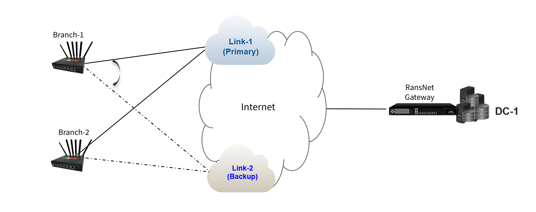
A remote branch with multiple WAN links (dual-WAN) connecting to a hub requires intelligent failover to ensure business continuity. The branch maintains a single VPN tunnel to the hub, but that tunnel automatically shifts between primary and backup WAN links when the primary fails. This architecture combines underlay resilience (automatic WAN failover) with overlay stability (single VPN tunnel endpoint), providing seamless failover without application-level awareness.
This guide configures a branch with dual WAN (primary broadband + backup 5G) connecting to a hub datacenter via a single VPN tunnel.
Overview
How It Works
Dual-WAN SD-WAN combines two resilience mechanisms:
- Dual WAN (underlay) — The branch router has two independent Internet connections (primary and backup)
- Single VPN (overlay) — One VPN tunnel from branch to hub; the tunnel shifts between WAN links as needed
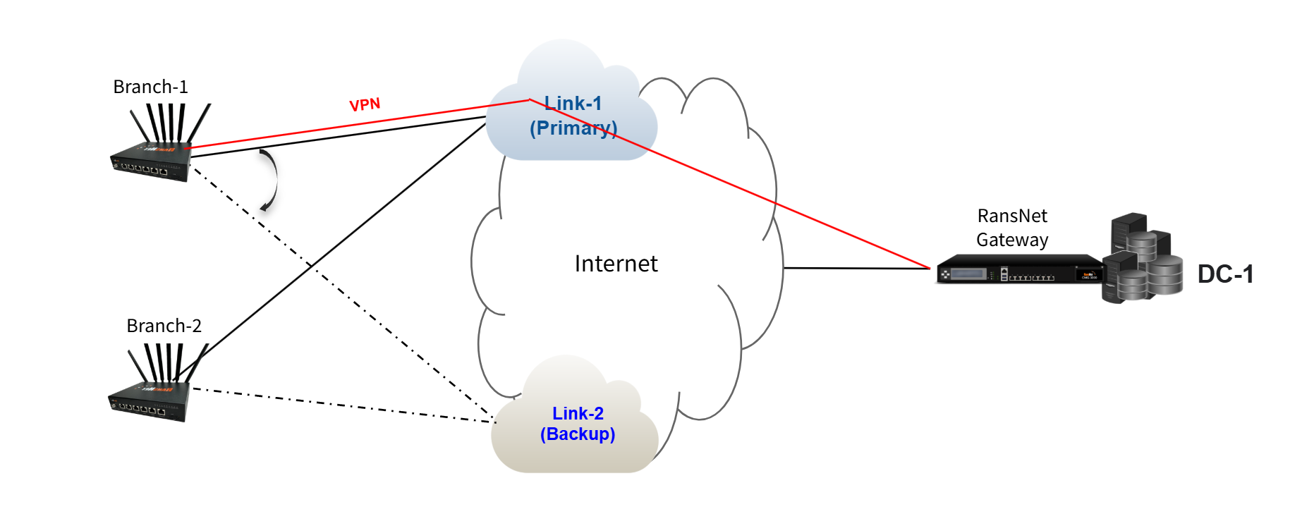
During normal operation, traffic uses the primary WAN link. When the primary link fails, the VPN tunnel automatically uses the backup WAN link without dropping traffic. The tunnel itself remains active; only the underlying Internet path changes. This provides transparent failover from the application's perspective.
Use Cases
| Scenario | Business Impact | Solution |
|---|---|---|
| Remote branch with critical operations | Branch loses productivity when primary ISP link fails | Dual-WAN failover keeps business systems online during ISP outages |
| Cost-optimized redundancy | Single premium ISP link is expensive; need backup without paying for two premium links | Combine expensive primary (fiber broadband) with cheaper backup (LTE), fail to LTE only when needed |
| Geographic diversity | Single ISP link may have localized outages affecting specific regions | Use different ISPs (fiber + LTE) or different ISP network paths to minimize correlated failures |
| 24/7 operational continuity | Downtime costs exceed the cost of redundant connectivity | Automatic failover ensures staff can work from branch office even during primary link failure |
Requirements
Infrastructure
- Hub (DC): RansNet gateway running SD-WAN with direct Internet access and static public IP
- Branch Router: RansNet branch router with dual WAN interfaces (Broadband + LTE, fiber + fiber, PPPoE + LTE, or other combinations)
- Internet Connectivity: Both WAN links must have independent paths to the hub's public IP; ISP-level peering ensures connectivity even if one ISP's network fails
- VPN Capability: Both hub and branch must support IPsec or WireGuard for tunnel setup
Network Planning
| Site | Network | Gateway | Role |
|---|---|---|---|
| Hub (DC) | vlan10: 192.168.10.0/24 | 192.168.10.1 | Datacenter networks |
| Hub (DC) | vlan20: 192.168.20.0/24 | 192.168.20.1 | Datacenter networks |
| Branch-A | vlan10: 192.168.11.0/24 | 192.168.11.1 | Branch LAN |
| Branch-A | vlan20: 192.168.21.0/24 | 192.168.21.1 | Branch LAN |
| Branch-B | vlan10: 192.168.12.0/24 | 192.168.12.1 | Branch LAN |
| Branch-B | vlan20: 192.168.22.0/24 | 192.168.22.1 | Branch LAN |
WAN Links
| Branch | Primary WAN | Secondary WAN | Primary Gateway | Backup Gateway |
|---|---|---|---|---|
| Branch-A (BR1) | Broadband (eth0) | 5G LTE (wwan0) | 10.18.18.1 | 100.67.35.5 |
| Branch-B (BR2) | Broadband (eth0) | 5G LTE (wwan0) | Similar pattern | Similar pattern |
Note
The hub datacenter can use any ISP or network path as long as both branch routers can reach the hub's public IP via both their WAN links. Different branches may use entirely different ISPs for primary and backup; what matters is that each branch has independent paths to the hub.
Network Behavior
Steady-State (Normal Operation)
When both branch WAN links are healthy:
- Branch router maintains two live default routes (one per ISP link)
- Router automatically elects primary WAN link (typically the first to come up or lowest metric, e.g., primary fiber, backup 5G)
- VPN tunnel uses the primary WAN link for all branch-to-hub traffic
- All datacenter-bound traffic flows through the VPN via the primary path
Tip
The branch router always uses the lowest metric default route to build the VPN tunnel. When the primary WAN link is available, the tunnel uses the primary path. When the primary WAN link fails, the tunnel automatically shifts to the backup WAN link (the only available default route).
Failover: Primary WAN Link Fails
When the branch's primary Internet connection drops:
- Primary WAN link becomes unavailable
- VPN tunnel automatically shifts to the backup WAN link (e.g., 5G LTE)
- Application traffic continues through the VPN tunnel (to DC), now routed via backup WAN
- Failover time is typically 2–5 seconds (depending on link detection timer)
- When primary WAN recovers, the VPN tunnel shifts back to the primary link
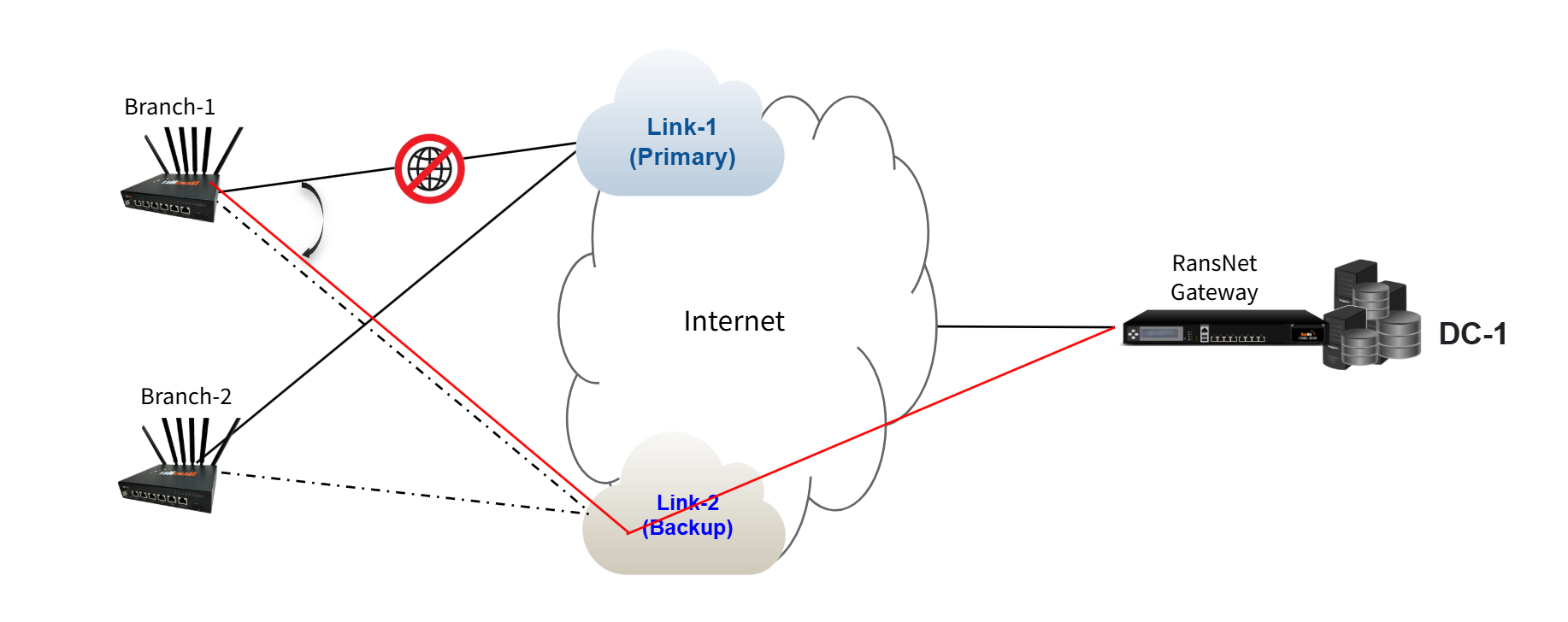
Key point: The VPN tunnel endpoint remains the same (the hub's public IP). Only the underlying Internet path changes. Applications and users do not experience service interruption.
Deployment
Architecture Principles
Before configuring, understand these core concepts:
| Concept | Description |
|---|---|
| Single VPN Tunnel | One VPN tunnel per branch-to-hub connection. Unlike dual-hub, there is no backup VPN — only backup underlay (WAN) paths. |
| Overlay Independence | The VPN tunnel is independent from the underlay WAN link. The tunnel endpoint (hub's public IP) remains the same; only the path changes. |
| Automatic Failover | When the primary WAN link fails, the kernel routing table automatically activates the secondary default route. The VPN tunnel automatically uses this new path without manual intervention. |
| Transparent to Applications | Applications don't detect failover because the VPN tunnel remains up. No reconnection is needed. |
Configuration Steps
Step 1: Configure Basic Network Settings and WAN Failover
Navigate to Device Settings → Network → Interfaces and configure interfaces for both gateway and branch routers. For basic network setting configuration, see Network Configuration.
For branch routers, configure automatic failover between the branch's two WAN links so that the VPN tunnel can seamlessly shift paths. See WAN Failover Configuration for detailed setup.
Key requirement: Use Option 2 (PBR with Tracking) to detect upstream failures, not just physical link down. This ensures the VPN tunnel shifts paths if the primary ISP link fails at the network level (not just at the physical port).
Step 2: Configure Hub Gateway VPN Instance
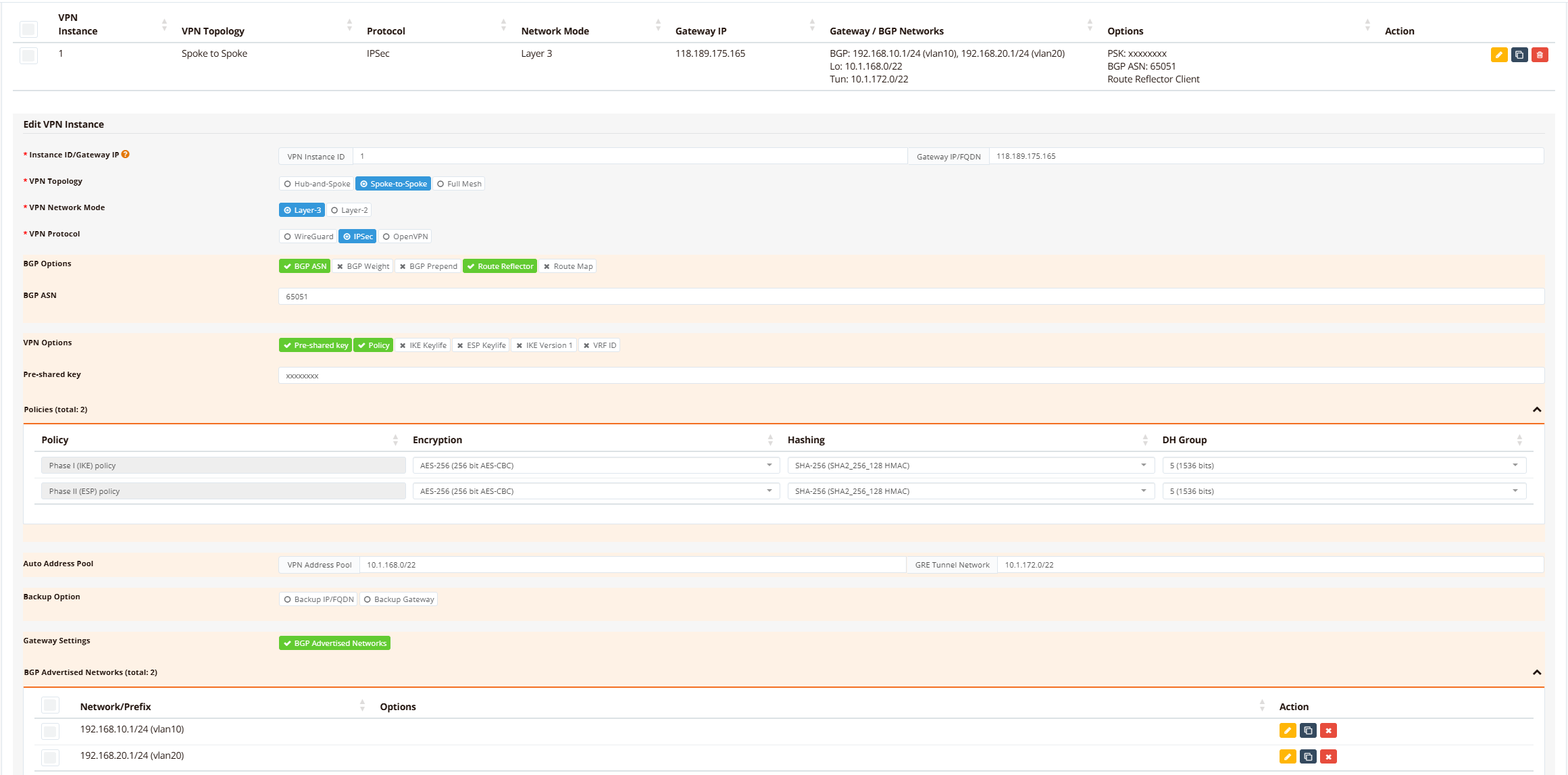
On the hub gateway device, navigate to Device Settings → SD-WAN → VPN, then click Add VPN Instance.
Define VPN topology and protocol settings:
- Topology: Spoke-to-Spoke (L3) or Hub-and-Spoke, depending on whether branches communicate directly with each other
- Protocol: IPsec or WireGuard (IPsec recommended for maximum interoperability)
- Encryption: AES-256/SHA256 (default)
- Advertised Networks: All hub datacenter networks (vlan10: 192.168.10.0/24, vlan20: 192.168.20.0/24)
Tip
If your hub gateway router has dual/redundant links with different public IPs, click Backup IP/FQDN to configure the secondary hub IP. Branches will automatically detect and use the backup IP if the primary hub IP becomes unreachable.
Step 3: Enroll Branch Routers into VPN Instance
On the hub gateway device, navigate to Device Settings → SD-WAN → VPN, scroll down to VPN Branches section.
Click Add VPN Branch and configure each branch:
- Select VPN instance and branch: From the dropdown list, select the pre-configured VPN instance, then select target branch router (branch name).
- Advertised Networks: All branch LAN networks (e.g., vlan10: 192.168.11.0/24, vlan20: 192.168.21.0/24)

Optionally enable tunnel tracking to monitor tunnel health and auto-reset if the tunnel becomes stuck or corrupted.
Step 4: Configure Firewall Access Rules
Navigate to Device Settings → Security → Firewall and configure firewall-access rules to permit traffic between sites based on your security policies.
For detailed firewall configuration, see Firewall Access Policies.
Verification
Use these commands to verify dual-WAN SD-WAN configuration and diagnose issues:
| What to Check | Command | Expected Output |
|---|---|---|
| Active WAN links | show interface eth0 and show interface wwan0 |
Both eth0 and wwan0 show UP with IP addresses assigned |
| Primary WAN selection | show ip route \| include 0.0.0.0 |
Two default routes visible; primary route (lower metric) selected as active |
| VPN tunnel status | show ipsec status |
Tunnel shows ESTABLISHED with active keepalive |
| Branch BGP adjacency | show ip bgp summary |
Neighbor shows UP with received prefixes |
| Learned branch routes | show ip bgp and show ip route bgp |
All branch networks present with BGP metric 200 |
| Connectivity to branch | ping <branch-gateway> |
Ping succeeds with round-trip latency ~5-10 ms (varies with distance) |
Example output on hub/gateway:
DC1-VM56# show ip interface
Interface    IP_Address       NetMask          Broadcast        MAC_Address
----------------------------------------------------------------------------------------------
lo           127.0.0.1        255.0.0.0        0.0.0.0          N/A
eth0         10.65.31.56      255.255.255.0    10.65.31.255     00:50:56:9b:72:48
vlan10       192.168.10.1     255.255.255.0    192.168.10.255   00:50:56:9b:72:48
vlan20       192.168.20.1     255.255.255.0    192.168.20.255   00:50:56:9b:72:48
vxlan1       10.1.172.1       255.255.252.0    10.1.175.255     76:7a:f0:30:39:43
DC1-VM56# show ipsec status
================================================================================
 IPSec Status
 Uptime  : 3 minutes, since Jun 07 14:35:12 2026
 Local   : 10.65.31.56
 Peers   : 2 established, 0 connecting
================================================================================

Peer                                State          Local Net         Remote Net             Tx       Rx  Uptime      IKE(Auth)    ESP
------------------------------------------------------------------------------------------------------------------------------------------------
b0-bb-8b-00-32-e0 (111.65.56.76)    ESTABLISHED    10.1.168.1/32     10.1.168.3/32       9.7KB    9.2KB  3 minutes   IKEv2(PSK)   AES-256/SHA256
d4-dd-0b-00-3d-00 (61.13.198.166)   ESTABLISHED    10.1.168.1/32     10.1.168.2/32       8.9KB    6.1KB  3 minutes   IKEv2(PSK)   AES-256/SHA256

DC1-VM56# show ip bgp summary

IPv4 Unicast Summary (VRF default):
BGP router identifier 10.65.31.56, local AS number 65051 vrf-id 0
BGP table version 6
RIB entries 11, using 2112 bytes of memory
Peers 2, using 1448 KiB of memory
Peer groups 1, using 64 bytes of memory

Neighbor        V         AS   MsgRcvd   MsgSent   TblVer  InQ OutQ  Up/Down State/PfxRcd   PfxSnt Desc
*10.1.172.2     4      65051       184       187        0    0    0 00:14:59            2        6 N/A
*10.1.172.3     4      65051        40        43        0    0    0 00:02:59            2        6 N/A

Total number of neighbors 2
* - dynamic neighbor
2 dynamic neighbor(s), limit 2000
DC1-VM56# show ip bgp

Instance default:
BGP table version is 6, local router ID is 10.65.31.56, vrf id 0
Default local pref 100, local AS 65051
Status codes:  s suppressed, d damped, h history, * valid, > best, = multipath,
               i internal, r RIB-failure, S Stale, R Removed
Nexthop codes: @NNN nexthop's vrf id, < announce-nh-self
Origin codes:  i - IGP, e - EGP, ? - incomplete
RPKI validation codes: V valid, I invalid, N Not found

   Network          Next Hop            Metric LocPrf Weight Path
*> 192.168.10.0/24  0.0.0.0                  0         32768 i
*>i192.168.11.0/24  10.1.172.2               0    100      0 i
*>i192.168.12.0/24  10.1.172.3               0    100      0 i
*> 192.168.20.0/24  0.0.0.0                  0         32768 i
*>i192.168.21.0/24  10.1.172.2               0    100      0 i
*>i192.168.22.0/24  10.1.172.3               0    100      0 i

Displayed  6 routes and 6 total paths
DC1-VM56# show ip route bgp
Codes: K - kernel route, C - connected, S - static, R - RIP,
       O - OSPF, I - IS-IS, B - BGP, E - EIGRP, N - NHRP,
       T - Table, v - VNC, V - VNC-Direct, A - Babel, F - PBR,
       f - OpenFabric,
       > - selected route, * - FIB route, q - queued, r - rejected, b - backup
       t - trapped, o - offload failure

B>* 192.168.11.0/24 [200/0] via 10.1.172.2, vxlan1, weight 1, 00:02:42
B>* 192.168.12.0/24 [200/0] via 10.1.172.3, vxlan1, weight 1, 00:02:49
B>* 192.168.21.0/24 [200/0] via 10.1.172.2, vxlan1, weight 1, 00:02:41
B>* 192.168.22.0/24 [200/0] via 10.1.172.3, vxlan1, weight 1, 00:02:48
DC1-VM56# ping 192.168.11.1 source 192.168.10.1
PING 192.168.11.1 (192.168.11.1) from 192.168.10.1 : 56(84) bytes of data.
64 bytes from 192.168.11.1: icmp_seq=1 ttl=64 time=4.76 ms
64 bytes from 192.168.11.1: icmp_seq=2 ttl=64 time=5.65 ms
64 bytes from 192.168.11.1: icmp_seq=3 ttl=64 time=4.91 ms
64 bytes from 192.168.11.1: icmp_seq=4 ttl=64 time=4.50 ms
64 bytes from 192.168.11.1: icmp_seq=5 ttl=64 time=4.30 ms

--- 192.168.11.1 ping statistics ---
5 packets transmitted, 5 received, 0% packet loss, time 4006ms
rtt min/avg/max/mdev = 4.299/4.823/5.647/0.462 ms
DC1-VM56#
Example output on branch:
BR1-COM5# show ip interface
Interface    IP_Address       NetMask          Broadcast        MAC_Address
----------------------------------------------------------------------------------------------
lo           127.0.0.1        255.0.0.0        0.0.0.0          N/A
eth0         10.18.18.212     255.255.255.0    10.18.18.255     d4:dd:0b:00:3d:00
vlan1        192.168.8.1      255.255.252.0    192.168.11.255   76:05:9c:93:b5:fd
vlan10       192.168.11.1     255.255.255.0    192.168.11.255   76:05:9c:93:b5:fd
vlan20       192.168.21.1     255.255.255.0    192.168.21.255   76:05:9c:93:b5:fd
wwan0        100.67.35.6      0.0.0.0          100.67.35.6      N/A
vxlan1       10.1.172.2       255.255.252.0    10.1.175.255     66:f8:63:f1:33:bf
BR1-COM5# show ip route
Codes: K - kernel route, C - connected, S - static, R - RIP,
       O - OSPF, B - BGP, N - NHRP, T - Table, v - VNC,
       V - VNC-Direct,
       > - selected route, * - FIB route, q - queued, r - rejected, b - backup
       t - trapped, o - offload failure

VRF default:
K * 0.0.0.0/0 [0/4] is directly connected, wwan0, 00:12:54
K>* 0.0.0.0/0 [0/0] via 100.67.35.5, wwan0, 00:13:03
K * 0.0.0.0/0 [0/2] via 10.18.18.1, eth0, src 10.18.18.212, 13:18:21
K * 10.1.168.2/32 [0/8] is directly connected, lo, 00:18:32
C>* 10.1.168.2/32 is directly connected, lo, 00:18:32
C>* 10.1.172.0/22 is directly connected, vxlan1, 00:18:27
C>* 10.18.18.0/24 is directly connected, eth0, 13:18:21
K * 10.18.18.0/24 [0/2] is directly connected, eth0, 13:18:21
K>* 10.18.18.1/32 [0/2] is directly connected, eth0, 13:18:21
K * 192.168.8.0/22 [0/5] is directly connected, vlan1, 13:18:41
C>* 192.168.8.0/22 is directly connected, vlan1, 13:18:41
B>* 192.168.10.0/24 [200/0] via 10.1.172.1, vxlan1, weight 1, 00:16:14
K * 192.168.11.0/24 [0/6] is directly connected, vlan10, 13:18:41
C>* 192.168.11.0/24 is directly connected, vlan10, 13:18:41
B>* 192.168.12.0/24 [200/0] via 10.1.172.1, vxlan1, weight 1, 00:03:59
B>* 192.168.20.0/24 [200/0] via 10.1.172.1, vxlan1, weight 1, 00:16:14
K * 192.168.21.0/24 [0/7] is directly connected, vlan20, 13:18:41
C>* 192.168.21.0/24 is directly connected, vlan20, 13:18:41
B>* 192.168.22.0/24 [200/0] via 10.1.172.1, vxlan1, weight 1, 00:03:58
BR1-COM5# show ipsec status
================================================================================
 IPSec Status
 Uptime  : 13 minutes, since Jun 07 06:26:47 2026
 Local   : 10.18.18.212
 Peers   : 1 established, 0 connecting
================================================================================

Peer                                State          Local Net         Remote Net             Tx       Rx  Uptime      IKE(Auth)    ESP
------------------------------------------------------------------------------------------------------------------------------------------------
118.189.175.165 (118.189.175.165)   ESTABLISHED    10.1.168.2/32     10.1.168.1/32       9.0KB   13.5KB  4 minutes   IKEv2(PSK)   AES-256/SHA256

BR1-COM5# show ip bgp summary

IPv4 Unicast Summary (VRF default):
BGP router identifier 10.18.18.212, local AS number 65051 vrf-id 0
BGP table version 6
RIB entries 11, using 1496 bytes of memory
Peers 1, using 712 KiB of memory
Peer groups 1, using 32 bytes of memory

Neighbor        V         AS   MsgRcvd   MsgSent   TblVer  InQ OutQ  Up/Down State/PfxRcd   PfxSnt Desc
10.1.172.1      4      65051       207       204        0    0    0 00:16:40            4        2 N/A

Total number of neighbors 1
BR1-COM5# show ip bgp

Instance default:
BGP table version is 6, local router ID is 10.18.18.212, vrf id 0
Default local pref 100, local AS 65051
Status codes:  s suppressed, d damped, h history, * valid, > best, = multipath,
               i internal, r RIB-failure, S Stale, R Removed
Nexthop codes: @NNN nexthop's vrf id, < announce-nh-self
Origin codes:  i - IGP, e - EGP, ? - incomplete
RPKI validation codes: V valid, I invalid, N Not found

   Network          Next Hop            Metric LocPrf Weight Path
*>i192.168.10.0/24  10.1.172.1               0    100      0 i
*> 192.168.11.0/24  0.0.0.0                  0         32768 i
*>i192.168.12.0/24  10.1.172.1               0    100      0 i
*>i192.168.20.0/24  10.1.172.1               0    100      0 i
*> 192.168.21.0/24  0.0.0.0                  0         32768 i
*>i192.168.22.0/24  10.1.172.1               0    100      0 i

Displayed  6 routes and 6 total paths
BR1-COM5# show ip route bgp
Codes: K - kernel route, C - connected, S - static, R - RIP,
       O - OSPF, B - BGP, N - NHRP, T - Table, v - VNC,
       V - VNC-Direct,
       > - selected route, * - FIB route, q - queued, r - rejected, b - backup
       t - trapped, o - offload failure

B>* 192.168.10.0/24 [200/0] via 10.1.172.1, vxlan1, weight 1, 00:16:45
B>* 192.168.12.0/24 [200/0] via 10.1.172.1, vxlan1, weight 1, 00:04:30
B>* 192.168.20.0/24 [200/0] via 10.1.172.1, vxlan1, weight 1, 00:16:45
B>* 192.168.22.0/24 [200/0] via 10.1.172.1, vxlan1, weight 1, 00:04:29
BR1-COM5# ping 192.168.10.1 source 192.168.11.1
PING 192.168.10.1 (192.168.10.1) from 192.168.11.1: 56 data bytes
64 bytes from 192.168.10.1: seq=0 ttl=64 time=6.139 ms
64 bytes from 192.168.10.1: seq=1 ttl=64 time=4.870 ms
64 bytes from 192.168.10.1: seq=2 ttl=64 time=5.485 ms
64 bytes from 192.168.10.1: seq=3 ttl=64 time=4.606 ms
64 bytes from 192.168.10.1: seq=4 ttl=64 time=4.922 ms

--- 192.168.10.1 ping statistics ---
5 packets transmitted, 5 packets received, 0% packet loss
round-trip min/avg/max = 4.606/5.204/6.139 ms
BR1-COM5# ping 192.168.20.1 source 192.168.11.1
PING 192.168.20.1 (192.168.20.1) from 192.168.11.1: 56 data bytes
64 bytes from 192.168.20.1: seq=0 ttl=64 time=5.227 ms
64 bytes from 192.168.20.1: seq=1 ttl=64 time=4.522 ms
64 bytes from 192.168.20.1: seq=2 ttl=64 time=4.701 ms
64 bytes from 192.168.20.1: seq=3 ttl=64 time=4.403 ms
64 bytes from 192.168.20.1: seq=4 ttl=64 time=4.568 ms

--- 192.168.20.1 ping statistics ---
5 packets transmitted, 5 packets received, 0% packet loss
round-trip min/avg/max = 4.403/4.684/5.227 ms
BR1-COM5#
Troubleshooting
Common Issues
| Symptom | Likely Cause | Solution |
|---|---|---|
| VPN tunnel fails to establish | Hub has firewall blocking IPsec from branch public IP | Verify hub firewall permits UDP 500, UDP 4500 (IPsec), or UDP 51821 (WireGuard) from branch WAN IPs; check NAT rules if hub is behind a router |
| Branch learns hub routes but hub doesn't learn branch routes | Branch networks are not advertised | Check BGP configuration advertises branch networks |
| Primary WAN fails but VPN tunnel doesn't failover to backup WAN | Backup WAN not configured; route metric not set correctly; tracking not detecting failure | Verify backup WAN (wwan0) is UP and has IP assigned; confirm eth0 metric = 10, wwan0 metric = 20 (show ip route); check PBR route (if using upstream tracking, show ip pbr) |
| Intermittent connectivity; tunnel flaps between WAN links | Tracking probe too aggressive; false failovers due to temporary packet loss | Increase tracking probe interval (e.g., timer 15s instead of 5s); change probe target to more reliable host (e.g., 8.8.8.8 instead of ISP gateway) |
| Hub can ping branch but branch cannot ping hub | Return traffic asymmetric; branch firewall blocking inbound ICMP | Verify hub firewall permits ICMP from branch LAN networks; check branch outbound firewall rules allow return traffic |
| Hub is not learning all branch routes | VPN instance not enrolling all branches | Navigate to Hub VPN Instance → VPN Branches; verify all branches are added and configured with correct advertised networks |
Debugging Commands
RansNet# show interface eth0
RansNet# show interface wwan0
RansNet# show ip route
RansNet# show ip route include 0.0.0.0
RansNet# show ipsec status
RansNet# show interface vxlan1
RansNet# show ip bgp summary
RansNet# show ip bgp
RansNet# show ip route bgp
RansNet# show logging system filter track
RansNet# ping <hub-gateway-ip>
Best Practices
Resilience
- Monitor both WAN links continuously — Configure tracking probes on every link; don't rely on physical UP status alone (a port may be UP but ISP network down)
- Diverse ISP providers — Use different ISP providers for primary and backup (fiber + LTE, fiber + fixed wireless) to minimize correlated outages
- Test failover regularly — Simulate primary link failure in controlled environments; document failover times and recovery sequence
- Enable tunnel tracking — Optional but recommended: auto-reset tunnels if they become stuck, reducing manual intervention
Performance
- Tune tracking probe interval — Satellite or wireless links may have higher latency; use longer intervals (30–60 seconds) to avoid false failovers
- Monitor tunnel health — Use
show ipsec statusto verify keepalive is active and packet counts are growing; stalled tunnel indicates stuck connection - Balance bandwidth — Primary WAN is typically more expensive (fiber) and used for normal traffic; backup WAN (LTE) should be sized for critical applications only
- Quality of Service (QoS) — Apply QoS policies to prioritize critical traffic (ERP, voice) over backup WAN during failover
Security
- Encrypt tunnel with strong algorithms — Use AES-256/SHA256 or better; avoid weaker algorithms
- Protect Pre-Shared Key (PSK) — Store PSK securely; rotate periodically; use unique PSKs for each branch-hub pair (not shared across multiple sites)
- Firewall on both sides — Hub and branch should both enforce firewall rules; asymmetric policies cause packet loss and debugging difficulty
- Disable unnecessary services — Disable DHCP, DNS, SSH on datacenter-facing VPN interfaces; minimize attack surface
- Monitor for rogue branches — Invalid PSK attempts in logs indicate possible intrusion attempts; alert on failed tunnel negotiations