Building GRE over IPSec VPN Between RansNet and Cisco IOS Routers
RansNet WAN solutions establish IPSec VPN tunnels with third-party products using standard IPSec protocols. This interoperability is important to complement customers' legacy setups and enable business operations in multi-vendor networks — sample guides are also available for Fortinet and Cisco Meraki. This document details how to set up spoke-to-spoke VPN tunnels between RansNet branch routers and a Cisco IOS router acting as the VPN hub.
Overview
Cisco DMVPN combines GRE over IPSec, NHRP, and dynamic routing to let peers auto-establish VPN tunnels directly between one another. But it carries a significant dependency: every peer must be reachable by every other peer, either directly over a public IP or indirectly from behind a NAT device. In real deployments, many branch routers have no public IP address due to carrier-grade NAT (CGNAT) — especially when connected over 4G/5G.
The practical alternative is a spoke-to-spoke topology: spokes route through the hub to reach one another. Only the hub needs a static public IP; the spokes can sit behind any form of WAN address, as long as they can reach the hub. Refer to VPN Topology for the topologies RansNet supports.
Building a spoke-to-spoke VPN among RansNet routers takes only a few clicks in the mfusion orchestrator. This document, however, demonstrates interoperability: a Cisco IOS router serves as the VPN hub, and the remote branches run RansNet SD-Branch routers (HSA/UA/CMG).
The key concepts of this setup:
- Provision a dummy hub gateway on mfusion and create an IPSec VPN instance that emulates the RansNet Gateway VPN settings.
- Assign all branch routers to that gateway VPN instance — exactly as in a typical RansNet SD-WAN provisioning.
- All VPN and routing configurations for the RansNet branch routers are centrally generated and pushed by the orchestrator; only the Cisco hub is configured manually.
Requirements
- A Cisco IOS router with a static public IP and IKEv2 support, acting as the VPN hub
- One or more RansNet branch routers (HSA/UA/CMG series), onboarded and online on mfusion — see Provisioning
- Pre-shared key and IKE/ESP security policies agreed for both sides
- IPSec (UDP 500/4500) reachability from the branches to the hub public IP
Topology
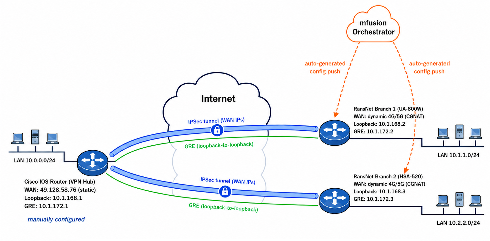
Topology Summary:
The Cisco IOS router (left) is the VPN hub with a static public IP and is configured manually. The two RansNet branch routers (right) sit behind dynamic 4G/5G WAN addresses (CGNAT) and receive their entire VPN and routing configuration automatically from mfusion. Each branch establishes an IPSec tunnel to the hub over the WAN IPs (blue), which carries a GRE tunnel between the loopback addresses (green); BGP runs over the GRE tunnels with the hub acting as route reflector. Spoke-to-spoke traffic between the branch LANs is routed through the hub.
The example in this document uses the following addressing:
| Device | Role | WAN IP | Loopback (IPSec) | GRE Tunnel IP | LAN Network |
|---|---|---|---|---|---|
| Cisco IOS router | VPN hub | 49.128.58.76 (static) |
10.1.168.1/32 |
10.1.172.1/22 |
10.0.0.0/24 (simulated on Loopback1) |
| Branch router 1 (COM17, UA-800W) | Spoke | Dynamic (4G/5G) | 10.1.168.2/32 |
10.1.172.2/22 |
10.1.1.0/24 |
| Branch router 2 (COM20, HSA-520) | Spoke | Dynamic (4G/5G) | 10.1.168.3/32 |
10.1.172.3/22 |
10.2.2.0/24 |
All devices share BGP AS 65051, with the hub acting as route reflector.
How GRE over IPSec works:
- Configure IPSec tunnels between hub and spokes using their external WAN IP addresses, and use IPSec to encrypt communications between the loopback IP addresses of hub and spokes.
- Configure GRE tunnels using the loopback IP addresses as tunnel source and destination — the GRE tunnels are therefore encrypted.
- Route traffic through the GRE tunnels — the actual traffic is therefore encrypted.
On the hub side (Cisco router):
- Accept all incoming IPSec tunnel requests via a dynamic crypto map — any source IP is accepted as long as it presents the correct pre-shared key.
- Configure an mGRE tunnel so individual tunnels per spoke are not needed, with a static NHRP map binding each spoke's GRE tunnel IP to its loopback IP.
Provisioning on mfusion
Step 1: Provision all branch routers and a dummy VPN gateway on mfusion — see Provisioning for the detailed guide. The branch routers should be online after this step.

Note
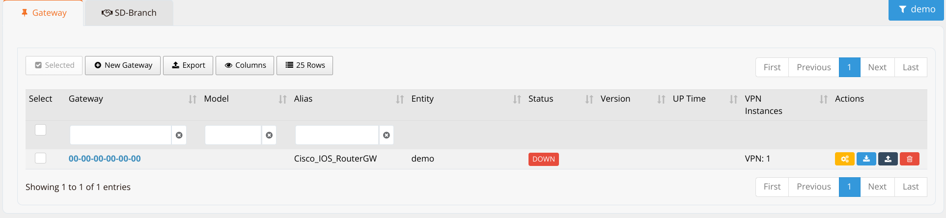
The dummy gateway is a placeholder host representing the Cisco router — it uses a placeholder MAC address (00-00-00-00-00-00) and never actually connects to mfusion.
Step 2: Import the hosts to the mfusion Orchestrator.
Import the dummy gateway host to Orchestrator → Gateway and attach an empty config template:
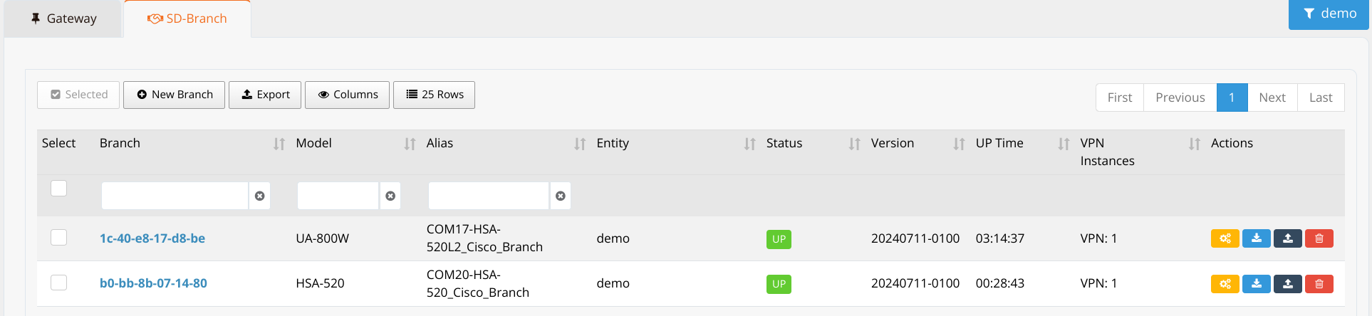
Import the branch routers to Orchestrator → SD-Branch and assign the default template (or copy from an existing configured host):
Step 3: On the dummy VPN gateway, create an IPSec VPN instance to emulate the Gateway VPN settings.
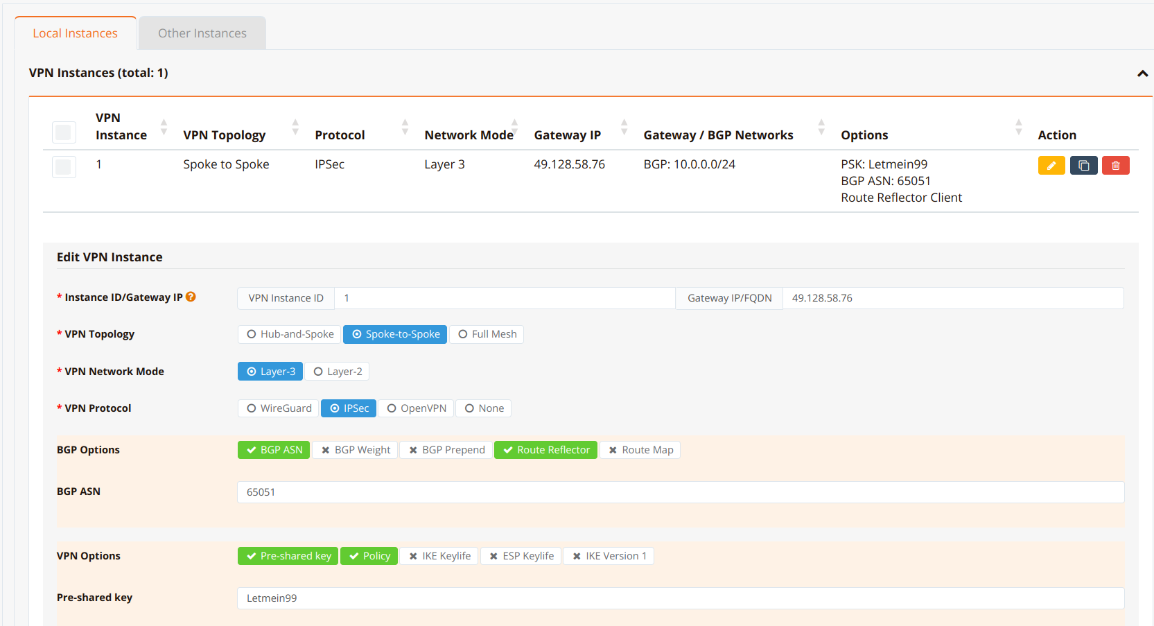
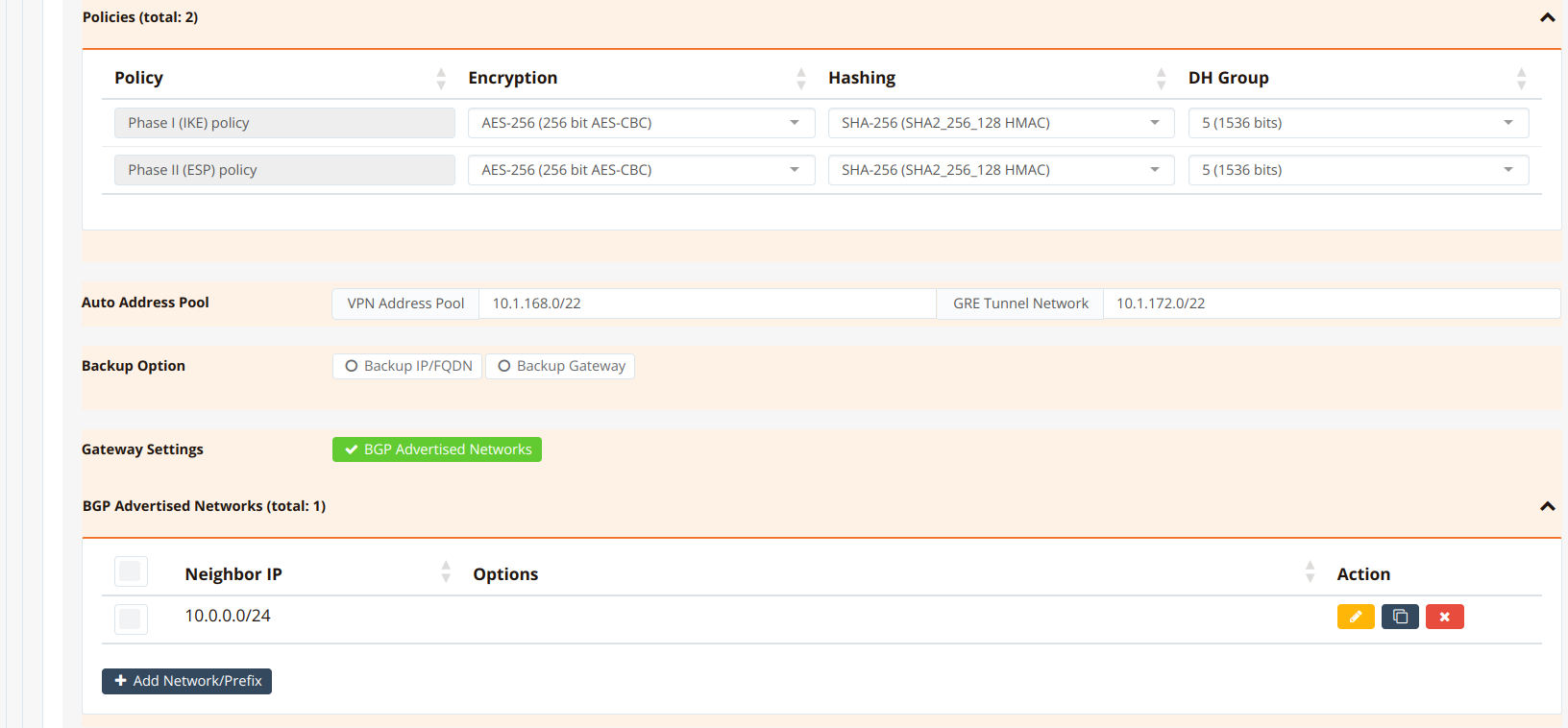
| Field | Example Value | Description |
|---|---|---|
| Instance ID / Gateway IP | 1 / 49.128.58.76 |
The Gateway IP/FQDN is the publicly accessible IP of the Cisco VPN hub. |
| VPN Topology | Spoke-to-Spoke |
Spokes reach one another through the hub. |
| VPN Network Mode | Layer-3 |
Routed overlay. |
| VPN Protocol | IPSec |
Standard IPSec for third-party interoperability. |
| BGP Options / BGP ASN | BGP ASN + Route Reflector, ASN 65051 |
Enables dynamic routing over the overlay; must match the Cisco BGP configuration. |
| Gateway / BGP Networks | 10.0.0.0/24 |
The hub-side LAN network advertised to the branches. |
| VPN Options / Pre-shared key | Letmein99 |
Must match the pre-shared key configured on the Cisco router. |
| Policy (Phase I & II) | AES-256 SHA-256 5 |
IKE and ESP security policies; must match the Cisco proposal/transform-set. |
Note
The Gateway IP, pre-shared key, and Phase I & II security policies configured here must be set identically in the Cisco configuration.
Step 4: Assign all branch routers to the VPN instance and configure the branch (remote) network for each router.
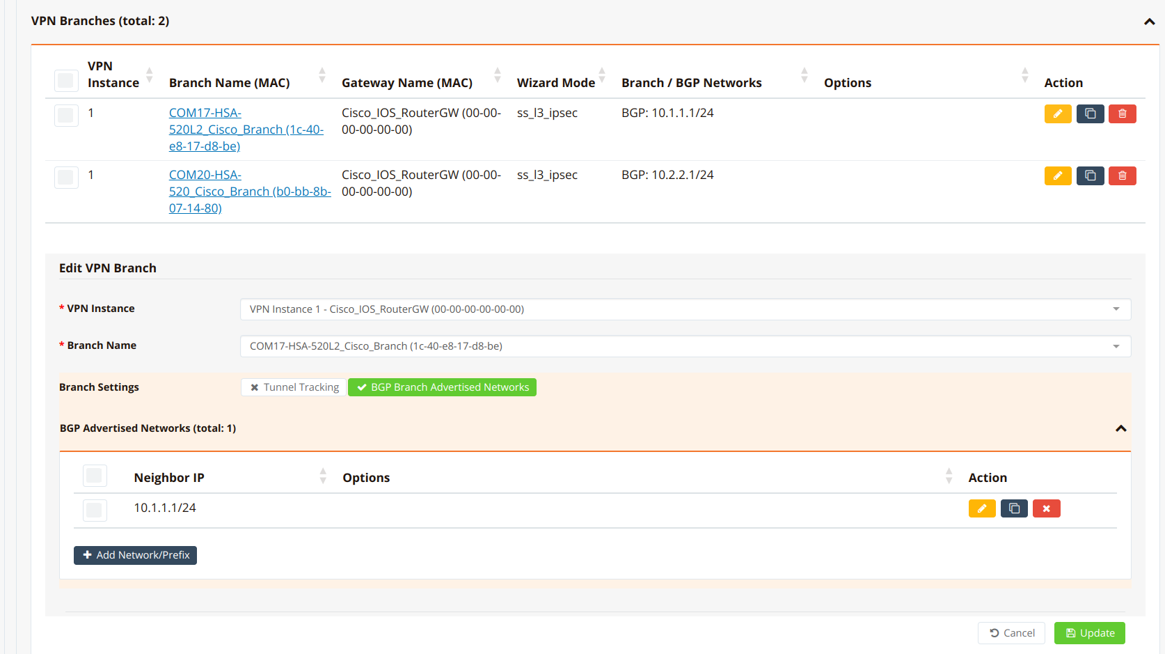
| Field | Example Value | Description |
|---|---|---|
| VPN Instance | VPN Instance 1 - Cisco_IOS_RouterGW |
The instance created in Step 3. |
| Branch Name | COM17-HSA-520L2_Cisco_Branch |
The branch router to attach. |
| Branch Settings | BGP Branch Advertised Networks |
Advertise the branch LAN over BGP. |
| BGP Advertised Networks | 10.1.1.1/24 |
The branch LAN network for this router. |
Note
If you have multiple branch routers, assign them all to the same VPN instance and change only the respective branch network setting.
Step 5: Click Apply Config. All settings are pushed to the RansNet branch routers, which then auto-initiate VPN tunnels to the Cisco router.
Note
The config push to the dummy VPN gateway will fail — this is expected (it is not a real device) and can be safely ignored.
Step 6: On the branch routers, configure firewall access rules to permit VPN traffic across the tunnel — a firewall template can be applied to all branch routers at once. NAT is automatically disabled for VPN tunnel networks, so no special NAT configuration is required. See Firewall Policies.
Configure the Cisco IOS Router
Using this simplified approach, below is a snip of the relevant Cisco router configuration to be configured manually. The commands are self-explanatory.
!
crypto ikev2 proposal RANSNET_IKE
 encryption aes-cbc-256
 integrity sha256
 group 5
!
crypto ikev2 policy RANSNET_IKE
 proposal RANSNET_IKE
!
crypto ikev2 profile RANSNET_IKE
 match identity remote any
 identity local address 49.128.58.76
 authentication remote pre-share key Letmein99
 authentication local pre-share key Letmein99
!
crypto ipsec transform-set RANSNET_ESP esp-aes 256 esp-sha256-hmac
 mode tunnel
!
crypto dynamic-map RANSNET_MAP 10
 set transform-set RANSNET_ESP
 set ikev2-profile RANSNET_IKE
 match address 100
!
crypto map RANSNET_IPSEC 10 ipsec-isakmp dynamic RANSNET_MAP
!
interface Loopback0
 description "GRE tunnel source"
 ip address 10.1.168.1 255.255.255.255
!
interface Loopback1
 description "simulated LAN network"
 ip address 10.0.0.1 255.255.255.0
!
interface Tunnel1
 ip address 10.1.172.1 255.255.252.0
 no ip redirects
 ip nhrp map 10.1.172.2 10.1.168.2
 ip nhrp map 10.1.172.3 10.1.168.3
 ip nhrp network-id 1
 tunnel source 10.1.168.1
 tunnel mode gre multipoint
!
interface GigabitEthernet0/0
 ip address x.x.x.x
 crypto map RANSNET_IPSEC
!
router bgp 65051
 bgp log-neighbor-changes
 timers bgp 5 15
 neighbor 0168_RansNet_SSL3IPSEC_1 peer-group
 neighbor 0168_RansNet_SSL3IPSEC_1 remote-as 65051
 neighbor 0168_RansNet_SSL3IPSEC_1 route-reflector-client
 neighbor 0168_RansNet_SSL3IPSEC_1 next-hop-self
 neighbor 0168_RansNet_SSL3IPSEC_1 soft-reconfiguration inbound
 neighbor 10.1.172.2 peer-group 0168_RansNet_SSL3IPSEC_1
 neighbor 10.1.172.3 peer-group 0168_RansNet_SSL3IPSEC_1
 network 10.0.0.0 mask 255.255.255.0
!
access-list 100 permit ip host 10.1.168.1 any
!
Note
10.1.168.xis the loopback IP range, auto-assigned by the orchestrator. The gateway (Cisco) always uses the first IP.10.1.172.xis the GRE tunnel IP range, auto-assigned by the orchestrator. The gateway uses the first IP.- The BGP configuration is optional if you do not wish to run dynamic routing for a small number of spoke sites.
- Newer IOS releases support dynamic BGP neighbors, so each neighbor does not need to be specified individually:
bgp listen range 10.1.172.0/22 peer-group 0168_RansNet_SSL3IPSEC_1
Auto-Generated Branch Configuration
For reference, below is a snip of the relevant CLI configuration on RansNet branch router 2 — auto-generated and pushed by the orchestrator in Step 5 (no manual configuration required):
!
interface gre1
 tunnel local 10.1.168.3 remote 10.1.168.1
 enable
 ip address 10.1.172.3/22
!
interface lo
 ip address 10.1.168.3/32
!
interface wwan0
 enable
!
interface vlan 1 1
 description "Default VLAN for all LAN ports"
 enable
 ip address 10.2.2.1/24
!
ip name-server 8.8.8.8 8.8.4.4
!
ip host portal.ransnet.com 118.189.175.170
!
ipsec ike-policy 1
 authentication psk
 policy AES-256 SHA-256 5
!
ipsec esp-policy 1
 policy AES-256 SHA-256 5
!
ipsec peer 49.128.58.76
 local-id b0-bb-8b-07-14-80
 local-net 10.1.168.3/32
 remote-net 10.1.168.1/32
 policy ike 1 esp 1
 psk Letmein99
!
router bgp 65051
 bgp timer 5 15
 neighbor 0168_RansNet_SSL3IPSEC_1 as-peer
 neighbor 0168_RansNet_SSL3IPSEC_1 as-remote 65051
 neighbor 0168_RansNet_SSL3IPSEC_1 next-hop-self
 neighbor 0168_RansNet_SSL3IPSEC_1 soft-reconfiguration
 neighbor 0168_RansNet_SSL3IPSEC_1 weight 0
 neighbor 10.1.172.1 as-peer 0168_RansNet_SSL3IPSEC_1
 network 10.2.2.1/24
!
The structure mirrors the Cisco side: IPSec protects loopback-to-loopback traffic (10.1.168.3/32 === 10.1.168.1/32), the GRE tunnel rides between the loopbacks, and BGP peers with the hub over the GRE tunnel IP.
Verification
| Items to Test | Command | Expected Outcome |
|---|---|---|
| IPSec sessions (hub) | show crypto session active (Cisco) |
One UP-IDLE session per branch, profile RANSNET_IKE, with an active IKEv2 SA. |
| BGP peering (hub) | show ip bgp summary (Cisco) |
Each branch GRE IP (10.1.172.x) listed with State/PfxRcd showing a prefix count (not Idle/Active). |
| Branch routes (hub) | show ip route bgp (Cisco) |
Each branch LAN (10.1.1.0/24, 10.2.2.0/24) learned via the corresponding GRE tunnel IP. |
| End-to-end (hub → branch) | ping <branch-LAN-IP> source 10.0.0.1 (Cisco) |
100% success rate, sourced from the hub LAN. |
| IPSec tunnel (branch) | show ipsec status (RansNet) |
SA ESTABLISHED with the hub, child SA 10.1.168.x/32 === 10.1.168.1/32 TUNNEL. |
| BGP peering (branch) | show ip bgp summary (RansNet) |
Hub neighbor 10.1.172.1 up with prefixes received. |
| End-to-end (branch → hub / branch) | ping <remote-LAN-IP> source <local-LAN-IP> (RansNet) |
0% packet loss to the hub LAN and to other branch LANs (via the hub). |
On the Cisco Hub
Verify IPSec session status:
TEST#sho crypto session active
Crypto session current status

Interface: GigabitEthernet0/0
Profile: RANSNET_IKE
Session status: UP-IDLE
Peer: 111.65.56.224 port 54377
  Session ID: 528
  IKEv2 SA: local 192.168.99.123/4500 remote 111.65.56.224/54377 Active

Interface: GigabitEthernet0/0
Profile: RANSNET
Session status: UP-IDLE
Peer: 119.234.10.4 port 30841
  Session ID: 294
  IKEv2 SA: local 192.168.99.123/4500 remote 119.234.10.4/30841 Active

Interface: GigabitEthernet0/0
Profile: RANSNET_IKE
Session status: UP-IDLE
Peer: 175.156.212.53 port 4500
  Session ID: 526
  IKEv2 SA: local 192.168.99.123/4500 remote 175.156.212.53/4500 Active

Interface: GigabitEthernet0/0
Profile: RANSNET_IKE
Session status: UP-IDLE
Peer: 119.234.10.4 port 24445
  Session ID: 529
  IKEv2 SA: local 192.168.99.123/4500 remote 119.234.10.4/24445 Active

TEST#
Verify BGP peering and learned branch routes:
TEST#sho ip bgp summary
BGP router identifier 10.7.7.11, local AS number 65051
BGP table version is 8, main routing table version 8
3 network entries using 432 bytes of memory
3 path entries using 240 bytes of memory
2/2 BGP path/bestpath attribute entries using 320 bytes of memory
0 BGP route-map cache entries using 0 bytes of memory
0 BGP filter-list cache entries using 0 bytes of memory
BGP using 992 total bytes of memory
BGP activity 5/2 prefixes, 5/2 paths, scan interval 60 secs

Neighbor        V           AS MsgRcvd MsgSent   TblVer  InQ OutQ Up/Down  State/PfxRcd
10.1.172.2      4        65051      51      55        8    0    0 00:04:02        1
10.1.172.3      4        65051    1044    1027        8    0    0 01:26:43        1

TEST#sho ip route bgp
Codes: L - local, C - connected, S - static, R - RIP, M - mobile, B - BGP
       D - EIGRP, EX - EIGRP external, O - OSPF, IA - OSPF inter area
       N1 - OSPF NSSA external type 1, N2 - OSPF NSSA external type 2
       E1 - OSPF external type 1, E2 - OSPF external type 2
       i - IS-IS, su - IS-IS summary, L1 - IS-IS level-1, L2 - IS-IS level-2
       ia - IS-IS inter area, * - candidate default, U - per-user static route
       o - ODR, P - periodic downloaded static route, H - NHRP, l - LISP
       a - application route
       + - replicated route, % - next hop override

Gateway of last resort is 192.168.99.1 to network 0.0.0.0

      10.0.0.0/8 is variably subnetted, 7 subnets, 3 masks
B        10.1.1.0/24 [200/0] via 10.1.172.2, 00:04:07
B        10.2.2.0/24 [200/0] via 10.1.172.3, 01:22:10
Test end-to-end connectivity from the hub LAN to each branch LAN:
TEST#ping 10.1.1.1 source 10.0.0.1
Type escape sequence to abort.
Sending 5, 100-byte ICMP Echos to 10.1.1.1, timeout is 2 seconds:
Packet sent with a source address of 10.0.0.1
!!!!!
Success rate is 100 percent (5/5), round-trip min/avg/max = 28/48/120 ms

TEST#ping 10.2.2.1 source 10.0.0.1
Type escape sequence to abort.
Sending 5, 100-byte ICMP Echos to 10.2.2.1, timeout is 2 seconds:
Packet sent with a source address of 10.0.0.1
!!!!!
Success rate is 100 percent (5/5), round-trip min/avg/max = 28/30/32 ms
TEST#
On the RansNet Branch Router
Verify the IPSec tunnel to the hub:
mbox-branch# show ipsec status
Connections:
49.128.58.76:  %any...49.128.58.76  IKEv2, dpddelay=10s
49.128.58.76:   local:  uses pre-shared key authentication
49.128.58.76:   remote: [49.128.58.76] uses pre-shared key authentication
49.128.58.76:   child:  10.1.168.2/32 === 10.1.168.1/32 TUNNEL, dpdaction=restart
Security Associations (1 up, 0 connecting):
49.128.58.76[1]: ESTABLISHED 5 minutes ago, 10.157.230.47[10.157.230.47]...49.128.58.76[49.128.58.76]
49.128.58.76[1]: IKEv2 SPIs: 01196420d033cb1d_i* f74ed74c774b54a4_r, rekeying disabled
49.128.58.76[1]: IKE proposal: AES_CBC_256/HMAC_SHA2_256_128/PRF_HMAC_SHA2_256/MODP_1536
49.128.58.76{1}:  INSTALLED, TUNNEL, reqid 1, ESP in UDP SPIs: c3d8077b_i e5615115_o
49.128.58.76{1}:  AES_CBC_256/HMAC_SHA2_256_128, 14972 bytes_i (198 pkts, 0s ago), 10759 bytes_o (141 pkts, 88s ago), rekeying disabled
49.128.58.76{1}:   10.1.168.2/32 === 10.1.168.1/32
mbox-branch#
Verify BGP peering with the hub and learned routes:
mbox-branch# show ip bgp summary

IPv4 Unicast Summary (VRF default):
BGP router identifier 10.157.230.47, local AS number 65051 vrf-id 0
BGP table version 5
RIB entries 5, using 680 bytes of memory
Peers 1, using 712 KiB of memory
Peer groups 1, using 32 bytes of memory

Neighbor        V         AS   MsgRcvd   MsgSent   TblVer  InQ OutQ  Up/Down State/PfxRcd   PfxSnt Desc
10.1.172.1      4      65051      1338      1368        0    0    0 00:05:16            2        1 N/A

Total number of neighbors 1

mbox-branch# show ip route bgp
Codes: K - kernel route, C - connected, S - static, O - OSPF,
       B - BGP, N - NHRP, T - Table, v - VNC, V - VNC-Direct,
       > - selected route, * - FIB route, q - queued, r - rejected, b - backup
       t - trapped, o - offload failure

B>* 10.0.0.0/24 [200/0] via 10.1.172.1, gre1, weight 1, 00:01:41
B>* 10.2.2.0/24 [200/0] via 10.1.172.3, gre1, weight 1, 00:05:19
Test end-to-end connectivity to the hub LAN and to the other branch LAN (spoke-to-spoke via the hub):
mbox-branch# ping 10.0.0.1 source 10.1.1.1
PING 10.0.0.1 (10.0.0.1) from 10.1.1.1: 56 data bytes
64 bytes from 10.0.0.1: seq=0 ttl=255 time=33.106 ms
64 bytes from 10.0.0.1: seq=1 ttl=255 time=32.053 ms
64 bytes from 10.0.0.1: seq=2 ttl=255 time=62.565 ms
64 bytes from 10.0.0.1: seq=3 ttl=255 time=62.243 ms
64 bytes from 10.0.0.1: seq=4 ttl=255 time=61.910 ms

--- 10.0.0.1 ping statistics ---
5 packets transmitted, 5 packets received, 0% packet loss
round-trip min/avg/max = 32.053/50.375/62.565 ms

mbox-branch# ping 10.2.2.1 source 10.1.1.1
PING 10.2.2.1 (10.2.2.1) from 10.1.1.1: 56 data bytes
64 bytes from 10.2.2.1: seq=0 ttl=63 time=228.013 ms
64 bytes from 10.2.2.1: seq=1 ttl=63 time=187.684 ms
64 bytes from 10.2.2.1: seq=2 ttl=63 time=148.846 ms
64 bytes from 10.2.2.1: seq=3 ttl=63 time=107.935 ms
64 bytes from 10.2.2.1: seq=4 ttl=63 time=56.509 ms

--- 10.2.2.1 ping statistics ---
5 packets transmitted, 5 packets received, 0% packet loss
round-trip min/avg/max = 56.509/145.797/228.013 ms
Troubleshooting
| Symptom | Likely Cause | Solution |
|---|---|---|
| IPSec tunnel does not establish | Pre-shared key or Phase I/II policy mismatch between mfusion VPN instance and Cisco configuration | Compare the PSK and IKE/ESP policies on both sides (show ipsec status on the branch; show crypto ikev2 sa on Cisco). Both must be identical. |
| Tunnel established but BGP neighbor stays down | GRE tunnel not up, or NHRP map missing for the spoke's loopback on the Cisco hub | Verify ip nhrp map <GRE-IP> <loopback-IP> exists for each spoke on Tunnel1, and check show interface gre1 on the branch. |
| Routes learned but ping fails between LANs | Branch firewall blocking tunnel traffic | Verify Step 6 firewall access rules permit traffic between the VPN LAN networks. |
| Branch cannot reach the hub at all | UDP 500/4500 blocked upstream, or wrong Gateway IP in the VPN instance | Confirm the hub public IP is reachable from the branch WAN, and that no upstream firewall blocks IPSec/NAT-T ports. |
| Config push fails for the dummy gateway | Expected behavior | The dummy gateway is not a real device — ignore the failed push (Step 5 note). |
Related Use Cases
- IPSec VPN to Cisco Meraki
- IPSec VPN to Fortinet
- VPN Topology — supported VPN topologies
- Provisioning — onboarding devices to mfusion