Deploying Highly Available Hotspot Gateways
This sample scenario covers an HSG high availability (HA) deployment that provides failover in case of hardware failure. HA is particularly important for on-premise deployments at large venues, where maximum service uptime is expected.
Use Cases
- Large hotels
- Large shopping malls
- Major tourism attractions
- Airports, stadiums, and other high-density venues
Topology
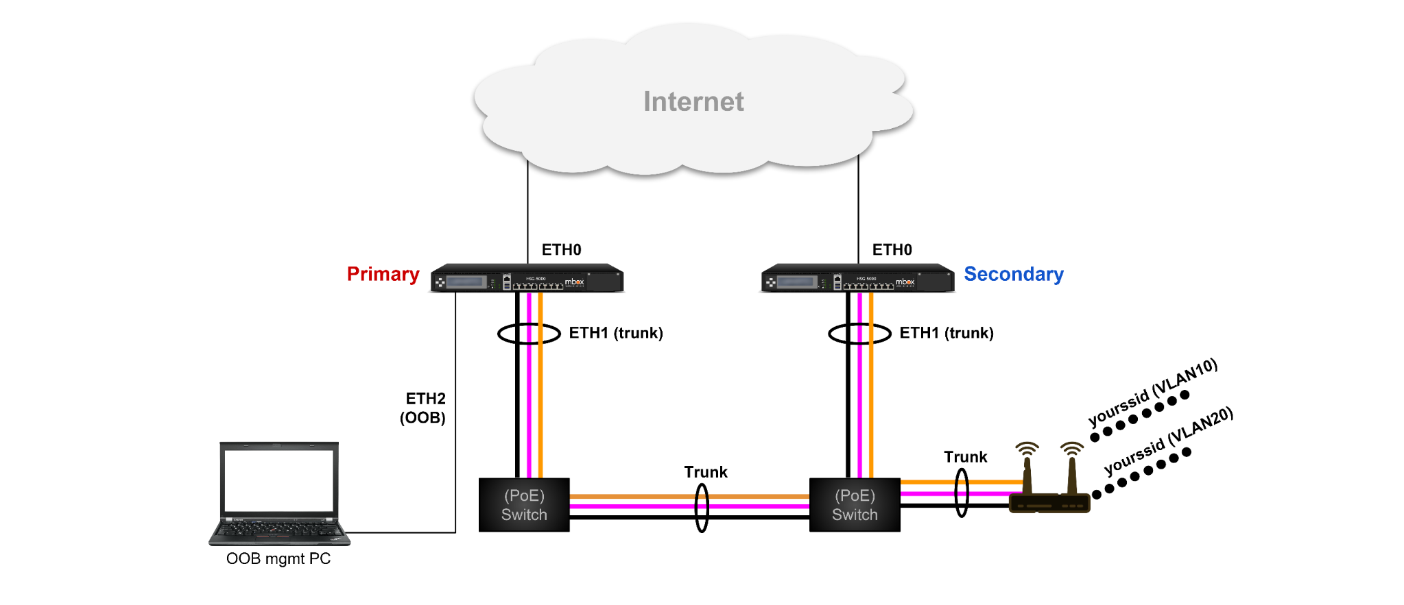
Topology Summary:
Two HSG units run side by side — Primary and Secondary, running in load-share (active/active) mode. Each unit connects its ETH0 (WAN) to the Internet and its ETH1 (LAN trunk) to a PoE switch; the two switches are interconnected by a trunk link. Access points connect to the PoE switches and broadcast SSIDs mapped to the hotspot VLANs (VLAN10, 20, 30, 40). ETH2 provides out-of-band management access, and ETH3 carries a dedicated HA link between the two units for failover detection and database sync.
The example configuration uses the following addressing:
| Item | HSG-1 (Primary) | HSG-2 (Secondary) |
|---|---|---|
| eth0 (WAN) | 172.16.30.19/24 (static) |
DHCP |
| eth1 (LAN trunk) | 192.168.8.9/22 |
192.168.8.10/22 |
VRRP group 10 — VIP 192.168.8.1 (LAN gateway / AP management) |
Priority 120 (MASTER) | Priority 80 |
VRRP group 13 — VIP 192.168.8.2 (anchor for hotspot VLAN10 & 30) |
Priority 120 (MASTER) | Priority 80 |
VRRP group 24 — VIP 192.168.8.3 (anchor for hotspot VLAN20 & 40) |
Priority 80 | Priority 120 (MASTER) |
| eth2 (OOB management) | 10.10.10.1/24 |
10.10.10.1/24 |
| eth3 (HA sync) | 10.9.9.3/29, VRRP group 9 VIP 10.9.9.1, priority 120, no preempt |
10.9.9.4/29, priority 80, no preempt |
| Hotspot client networks | VLAN10 172.16.0.0/16 · VLAN20 172.17.0.0/16 · VLAN30 172.18.0.0/16 · VLAN40 172.19.0.0/16 |
Identical |
How It Works
The HSG runs the hotspot services, stores user accounts, and keeps hotspot sessions and user access records. Both HSG units must therefore be identical, so that failover is stateful and seamless to connected users, with all databases and records synced and maintained. Three key HSG features work together to achieve this:
VRRP
VRRP detects the hardware active/standby status and steers user traffic to the alive (active) unit — see VRRP for the feature reference.
- Provision a dedicated link or VLAN between the HA units for failover detection and data sync (eth3 in this example).
- Configure VRRP groups on all participating VLANs, with the respective priorities on the MASTER and BACKUP units.
- VRRP attaches a virtual IP (VIP) to the active unit's interface and installs a VIP host route on the MASTER (active) unit.
- Configure tracking on the groups where the unit is MASTER (e.g.,
track icmp 1.1.1.1 120— ICMP probes to an upstream host) so VRRP automatically fails over to the peer when upstream connectivity is lost. A tracked group needs no explicitenable— tracking automatically enables or disables the group's participation based on the probe result. See Tracking VRRP.
Hotspot Tracking
Hotspot tracking determines which unit activates its hotspot service, by checking for the VRRP VIP host route (track route <vip>/32 <interval> under each hotspot instance, with <interval> in seconds — see Tracking).
Since the HSG can run multiple hotspot instances for multiple VLANs, one group of VLANs/hotspot instances can be active on the primary unit and another group active on the secondary unit — achieving load sharing (active-active) across the pair. Within each VLAN instance, the two units still operate in active/standby mode.
- On the active unit — tracking activates the hotspot service for its VLAN. The configured
hotspot-serverIP becomes the default gateway for clients and answers client DHCP requests, so user traffic passes through the active unit for this VLAN. - On the standby unit — tracking turns the hotspot service off for its VLAN, so the standby unit does not answer client DHCP requests and passes no traffic.
- On failover — the standby unit takes over the VRRP VIP (and therefore the VIP host route). Hotspot tracking activates the hotspot service, creating the tunnel interface that takes over the
hotspot-serverIP, so client traffic is routed to the standby unit (now active).
Hotspot configuration guidelines:
- Both units must have an identical hotspot configuration (the same set of
security hotspot xxblocks) — see the configuration differences below for the few settings that intentionally differ. - Do not enable
dhcp-serveron the hotspot VLAN interfaces — the hotspot engine is already a DHCP server (or can relay to an upstream DHCP server). - Do not configure an IP address on the hotspot VLAN interfaces — instead, configure
hotspot-server x.x.x.x ...under each hotspot instance. - Configure
client-network x.x.x.xfor the client IP subnet, and optionally aclient-dhcp xxxscope. - Configure
client-static x.x.x.x— after a failover, a client still holds the IP issued by the previously active unit. To the newly active unit, that IP looks like it came from an external DHCP server; this command authorizes such client IPs.
Hotspot Database Sync
Database sync replicates user account databases, historical records, and active "sticky" sessions from the primary to the secondary unit, so both units stay identical and the user experience is seamless during failover. This is configured using the mfusion sync CLI feature — see System Sync for the full reference.
- Each unit tracks the HA VRRP VIP (
10.9.9.1) usingtrack route— VRRP determines which unit is primary (the unit holding the VIP), andmfusion syncfollows that same VIP to decide its own read/write role. - Configure
remote-ip/local-ipwith each unit's own IP/MAC so the two units can replicate the hotspot database (user accounts, sessions, and history) between them: - At initial setup, enable HA on the primary unit first, then the secondary — then run
rejoinon the secondary to force an immediate full sync rather than waiting for it to catch up on its own.
Don't track the VIP via track icmp/track tcp
Both HSG units sit on the same L2 segment as the VIP, so either one can ping or reach it over TCP regardless of which unit actually owns it — a probe would always succeed and both units could conclude they're primary (split-brain). track route instead checks whether this unit's own routing table holds the VIP host route, which only VRRP installs on the unit currently acting as MASTER. See System Sync — Determining System Role.
Note
In this example, AP management IPs are assigned statically or by an external DHCP server. If you choose to issue DHCP for AP management IPs from the HSGs on eth1, split the DHCP scopes between the two units (e.g., 192.168.8.50–192.168.9.254 on HSG-1 and 192.168.10.1–192.168.11.254 on HSG-2) — both units' DHCP services are active simultaneously.
Active-Active Deployment Notes
- Configure multiple VRRP groups with multiple VIPs, split between the two gateways, so each VLAN's traffic is load-shared to its respective gateway. In this sample, VLAN10 & 30 are MASTER/active on the primary unit, and VLAN20 & 40 are MASTER/active on the secondary unit.
- Configure one dedicated VLAN/link with its own HA VRRP group for sync purposes (VIP on the primary) between the two gateways.
- On both units, point
captive.ransnet.comto the sync VRRP VIP. While the primary gateway is UP, it acts as the RADIUS and portal server for both units; when the primary is DOWN, the sync VIP moves to the secondary unit, which then uses its local RADIUS and portal. - Set
preempt noon the HA sync VRRP group, so that when the failed primary comes back online it first re-syncs with the secondary (currently active) unit instead of immediately resuming as primary. Keep preempt (the default) on the other VRRP groups, so that when both units are up, traffic is load-shared across both (active-active). - Enable
client-local-access yeson each hotspot instance. By default, client traffic can only exit via WAN/eth0 — but while the primary is alive, the portal is hosted on the primary, and clients connected through the secondary must reach that portal via the HA link. This command permits that access. - On each unit, add RADIUS clients for the VRRP VIP and both peer IPs, so the RADIUS server accepts requests from the peer during active-active operation and failover.
Deployment Steps
Step 1: Physical connections
- Connect both HSG eth0 (WAN) ports to the Internet routers (or switches, or link balancers, depending on your WAN setup).
- Connect both HSG eth1 (LAN) ports to the LAN switches.
- Connect the two HSG eth3 ports for the HA sync link.
- Connect eth2 to the management PC when needed — configure the PC with a static IP in
10.10.10.0/24(e.g.,10.10.10.10), then open the mbox GUI athttp://10.10.10.1(default loginmboxadmin/Letthem0ut7&). - Connect the APs to the LAN PoE switches.
Step 2: Switch configuration
- Use the default VLAN1 as the management VLAN for the APs/WLC.
- Add all hotspot VLANs on the switches (VLAN10, 20, 30, 40, 50), configure all switch ports in trunk mode, and permit all VLANs on each port (default).
Step 3: AP configuration
- AP management IPs come from network
192.168.8.0/22— assigned statically or by an external DHCP server (or from the HSGs with split scopes; see the note above). - IPs from
192.168.8.1to192.168.8.49are reserved for the WLC or other infrastructure devices. - Configure the APs to broadcast the desired SSIDs and map each SSID to its pre-configured VLAN — refer to the respective AP vendor documentation for SSID-to-VLAN mapping.
- The HSG default pre-configured hotspot VLANs are VLAN10, 20, 30, and 40, with auto roaming between VLANs enabled — see Hotspot Roaming.
Configuration Reference
The complete configurations of both units are shown below, followed by a summary of the differences.
HSG-1 (Primary)
!
hostname HSG-1
!
interface eth0
 description "Connection to WAN"
 enable
 ip address 172.16.30.19/24
!
interface eth1
 description "VRRP VIP to make vlan10&30 as backup, vlan20&40 as active"
 enable
 ip address 192.168.8.9/22
 vrrp-group 10
  priority 120
  virtual_ipaddress 192.168.8.1
  track icmp 1.1.1.1 120
  enable
 vrrp-group 13
  priority 120
  virtual_ipaddress 192.168.8.2
  track icmp 1.1.1.1 120
 vrrp-group 24
  priority 80
  virtual_ipaddress 192.168.8.3
  enable
!
interface eth2
 description OOB-Mgmt
 enable
 ip address 10.10.10.1/24
!
interface eth3
 description "HA sync"
 enable
 ip address 10.9.9.3/29
 vrrp-group 9
  priority 120
  preempt no
  virtual_ipaddress 10.9.9.1
  track icmp 1.1.1.1 120
  enable
!
interface vlan 1 10
 description "hotspot VLAN10"
 enable
!
interface vlan 1 20
 description "hotspot VLAN20"
 enable
!
interface vlan 1 30
 description "hotspot VLAN30"
 enable
!
interface vlan 1 40
 description "hotspot VLAN40"
 enable
!
interface loopback
 enable
 ip address 2.1.2.1/32
!
ip dhcp-server start
!
ip name-server 8.8.8.8 8.8.4.4
ip host macc.ransnet.com 2.1.2.1 rewrite
ip host mail 127.0.0.1
ip host mysqldb 127.0.0.1
ip host captive.ransnet.com 10.9.9.1 rewrite
!
ip ntp-server 203.211.159.1 62.201.225.9
!
ip default-gateway 172.16.30.1
!
firewall-input 20 permit all tcp dport 80 src 10.0.0.0/8 admin remark "web mgmt"
firewall-input 21 permit all tcp dport 22 src 10.0.0.0/8 remark "SSH from OOB"
firewall-input 30 permit inbound eth3 tcp dport 80 remark "portal access from HA peer"
firewall-input 31 permit inbound eth3 tcp dport 443 remark "portal access from HA peer"
firewall-input 32 permit inbound eth3 udp dport 1812 remark "RADIUS access from HA peer"
firewall-input 33 permit inbound eth3 udp dport 1813 remark "RADIUS access from HA peer"
firewall-input 999 permit outbound eth0
!
firewall-access 10 permit outbound eth0 remark "access to Internet"
firewall-access 11 permit outbound eth3 remark "access to HA portal/radius"
!
firewall-snat 10 overload outbound eth0 remark "access to Internet"
firewall-snat 11 overload outbound eth3 remark "access to HA portal/radius"
!
security radius-server
 client 10.9.9.1 key testing123 name HA-Peer-VIP
 client 10.9.9.3 key testing123 name HA-Peer-1
 client 10.9.9.4 key testing123 name HA-Peer-2
 start
!
security hotspot vlan10
 hotspot-server 172.16.0.1 ports 5011 5012
 client-network 172.16.0.0 255.255.0.0
 client-dhcp 172.16.0.100 255.255.0.0 lease 3600
 client-local-access yes
 client-sticky start 1
 client-sticky-vlanlist vlan10,vlan20,vlan30,vlan40
 bypass-mac radius
 radius-server captive.ransnet.com testing123
 hotspot-portal https://captive.ransnet.com/pid/portal/login.php
 track route 192.168.8.2/32 120
!
security hotspot vlan20
 hotspot-server 172.17.0.1 ports 5021 5022
 client-network 172.17.0.0 255.255.0.0
 client-dhcp 172.17.0.100 255.255.0.0 lease 3600
 client-local-access yes
 client-sticky start 1
 client-sticky-vlanlist vlan10,vlan20,vlan30,vlan40
 bypass-mac radius
 radius-server captive.ransnet.com testing123
 hotspot-portal https://captive.ransnet.com/pid/portal/login.php
 track route 192.168.8.3/32 120
!
security hotspot vlan30
 hotspot-server 172.18.0.1 ports 5031 5032
 client-network 172.18.0.0 255.255.0.0
 client-dhcp 172.18.0.100 255.255.0.0 lease 3600
 client-local-access yes
 client-sticky start 1
 client-sticky-vlanlist vlan10,vlan20,vlan30,vlan40
 bypass-mac radius
 radius-server captive.ransnet.com testing123
 hotspot-portal https://captive.ransnet.com/pid/portal/login.php
 track route 192.168.8.2/32 120
!
security hotspot vlan40
 hotspot-server 172.19.0.1 ports 5041 5042
 client-network 172.19.0.0 255.255.0.0
 client-dhcp 172.19.0.100 255.255.0.0 lease 3600
 client-local-access yes
 client-sticky start 1
 client-sticky-vlanlist vlan10,vlan20,vlan30,vlan40
 bypass-mac radius
 radius-server captive.ransnet.com testing123
 hotspot-portal https://captive.ransnet.com/pid/portal/login.php
 track route 192.168.8.3/32 120
!
HSG-2 (Secondary)
!
hostname HSG-2
!
interface eth0
 description "Connection to WAN"
 enable
 ip address dhcp
!
interface eth1
 description "VRRP VIP to make vlan10&30 as backup, vlan20&40 as active"
 enable
 ip address 192.168.8.10/22
 vrrp-group 10
  priority 80
  virtual_ipaddress 192.168.8.1
  enable
 vrrp-group 13
  priority 80
  virtual_ipaddress 192.168.8.2
  enable
 vrrp-group 24
  priority 120
  virtual_ipaddress 192.168.8.3
  track icmp 1.1.1.1 120
!
interface eth2
 description OOB-Mgmt
 enable
 ip address 10.10.10.1/24
!
interface eth3
 description "VRRP VIP to determine portal&radius"
 enable
 ip address 10.9.9.4/29
 vrrp-group 9
  priority 80
  preempt no
  virtual_ipaddress 10.9.9.1
  enable
!
interface vlan 1 10
 description "hotspot VLAN10"
 enable
!
interface vlan 1 20
 description "hotspot VLAN20"
 enable
!
interface vlan 1 30
 description "hotspot VLAN30"
 enable
!
interface vlan 1 40
 description "hotspot VLAN40"
 enable
!
interface loopback
 enable
 ip address 2.1.2.1/32
!
ip dhcp-server start
!
ip name-server 8.8.8.8 8.8.4.4
ip host macc.ransnet.com 2.1.2.1 rewrite
ip host mail 127.0.0.1
ip host mysqldb 127.0.0.1
ip host captive.ransnet.com 10.9.9.1 rewrite
!
ip ntp-server 203.211.159.1 62.201.225.9
!
firewall-input 20 permit all tcp dport 80 src 10.0.0.0/8 admin remark "web mgmt"
firewall-input 21 permit all tcp dport 22 src 10.0.0.0/8 remark "SSH from OOB"
firewall-input 30 permit inbound eth3 tcp dport 80 remark "portal access from HA peer"
firewall-input 31 permit inbound eth3 tcp dport 443 remark "portal access from HA peer"
firewall-input 32 permit inbound eth3 udp dport 1812 remark "RADIUS access from HA peer"
firewall-input 33 permit inbound eth3 udp dport 1813 remark "RADIUS access from HA peer"
!
firewall-access 10 permit outbound eth0 remark "access to Internet"
firewall-access 11 permit outbound eth3 remark "access to HA portal/radius"
firewall-input 999 permit outbound eth0
!
firewall-snat 10 overload outbound eth0 remark "access to Internet"
firewall-snat 11 overload outbound eth3 remark "access to HA portal/radius"
!
security radius-server
 client 10.9.9.1 key testing123 name HA-Peer-VIP
 client 10.9.9.3 key testing123 name HA-Peer-1
 client 10.9.9.4 key testing123 name HA-Peer-2
 start
!
security hotspot vlan10
 hotspot-server 172.16.0.1 ports 5011 5012
 client-network 172.16.0.0 255.255.0.0
 client-dhcp 172.16.0.100 255.255.0.0 lease 3600
 client-local-access yes
 client-sticky start 1
 client-sticky-vlanlist vlan10,vlan20,vlan30,vlan40
 bypass-mac radius
 radius-server captive.ransnet.com testing123
 hotspot-portal https://captive.ransnet.com/pid/portal/login.php
 track route 192.168.8.2/32 120
!
security hotspot vlan20
 hotspot-server 172.17.0.1 ports 5021 5022
 client-network 172.17.0.0 255.255.0.0
 client-dhcp 172.17.0.100 255.255.0.0 lease 3600
 client-local-access yes
 client-sticky start 1
 client-sticky-vlanlist vlan10,vlan20,vlan30,vlan40
 bypass-mac radius
 radius-server captive.ransnet.com testing123
 hotspot-portal https://captive.ransnet.com/pid/portal/login.php
 track route 192.168.8.3/32 120
!
security hotspot vlan30
 hotspot-server 172.18.0.1 ports 5031 5032
 client-network 172.18.0.0 255.255.0.0
 client-dhcp 172.18.0.100 255.255.0.0 lease 3600
 client-local-access yes
 client-sticky start 1
 client-sticky-vlanlist vlan10,vlan20,vlan30,vlan40
 bypass-mac radius
 radius-server captive.ransnet.com testing123
 hotspot-portal https://captive.ransnet.com/pid/portal/login.php
 track route 192.168.8.2/32 120
!
security hotspot vlan40
 hotspot-server 172.19.0.1 ports 5041 5042
 client-network 172.19.0.0 255.255.0.0
 client-dhcp 172.19.0.100 255.255.0.0 lease 3600
 client-local-access yes
 client-sticky start 1
 client-sticky-vlanlist vlan10,vlan20,vlan30,vlan40
 bypass-mac radius
 radius-server captive.ransnet.com testing123
 hotspot-portal https://captive.ransnet.com/pid/portal/login.php
 track route 192.168.8.3/32 120
!
Configuration Differences
The two units are intentionally almost identical — only the following differ:
| Item | HSG-1 (Primary) | HSG-2 (Secondary) |
|---|---|---|
| Hostname | HSG-1 |
HSG-2 |
| eth0 (WAN) | Static 172.16.30.19/24 + ip default-gateway 172.16.30.1 |
ip address dhcp (gateway learned from DHCP) |
| eth1 IP | 192.168.8.9/22 |
192.168.8.10/22 |
| VRRP priorities (groups 10, 13 / 24) | 120, 120 / 80 — MASTER for VLAN10 & 30 |
80, 80 / 120 — MASTER for VLAN20 & 40 |
VRRP tracking (track icmp 1.1.1.1 120) |
On groups 10, 13, and 9 — the groups it masters | On group 24 — the group it masters |
| eth3 (HA sync) | 10.9.9.3/29, VRRP group 9 priority 120 |
10.9.9.4/29, VRRP group 9 priority 80 |
All security hotspot blocks, RADIUS clients, host entries, and SNAT/access rules are identical on both units.
Verification
| Items to Test | Command / Action | Expected Outcome |
|---|---|---|
| VRRP states | show ip vrrp on both units |
HSG-1 is MASTER (holds VIP) for groups 10, 13, and 9; HSG-2 is MASTER for group 24. Backups show (backup). See VRRP Verification. |
| Hotspot services per unit | show security hotspot clients on both units |
VLAN10 & 30 clients are served by HSG-1; VLAN20 & 40 clients by HSG-2. |
| Client connectivity | Connect a client to each SSID/VLAN | Client receives an IP from the hotspot instance's client-dhcp scope, portal loads, and Internet access works after login. |
| Failover | Disconnect HSG-1's WAN (eth0) or power it off | VIPs for groups 10, 13, and 9 move to HSG-2 within seconds (show ip vrrp); connected users keep their IP and session without re-login (sticky session sync). |
| Failback | Restore HSG-1 | Group 9 (HA sync, preempt no) stays on HSG-2 until re-sync; other groups preempt back so traffic is load-shared again. |
| Database sync | Create a test hotspot user while HSG-1 is active, then check HSG-2 | The account and session records appear on HSG-2. |
Related Features
- System Sync —
mfusion syncreference: database and file replication, primary/secondary role determination - VRRP — VRRP groups, priorities, and tracking
- Tracking Features — interface and route tracking
- Hotspot Instance — hotspot instance configuration reference
- Hotspot Roaming — auto roaming between hotspot VLANs
- UAM / AAA / RADIUS — authentication and user management