Starlink Bonding (Same-Subnet WAN Bonding)
Some WAN links cannot use conventional Multi-WAN load balancing because every link is issued an IP address — and a default gateway — from the same network. This is the normal behaviour of multiple Starlink terminals on a shared service plan: every dish hands out an address from the same CGNAT pool with an identical gateway, so the router has no way to tell the links apart by gateway or subnet. This guide bonds several such links into a single, load-balanced, self-healing uplink using per-link VRF isolation combined with BGP-driven Equal-Cost Multi-Path (ECMP) routing.
The pattern is not specific to Starlink — it applies to any deployment where multiple WAN links share identical addressing: several SIMs from the same carrier/APN, multiple fiber drops from one wholesale ISP, or any other same-subnet uplink combination.
Overview
The Problem — Multiple WAN Links, One Shared Network
Conventional Multi-WAN (see WAN Failover) assumes each WAN link is issued a distinct network and gateway, so the router can select or track a path by matching against that link's specific gateway. When every link instead shares one identical gateway address, that assumption breaks down — the kernel and standard tracking/PBR logic cannot distinguish one link from another, and conventional Multi-WAN load balancing does not work.
The Solution — Per-Link VRF + BGP ECMP
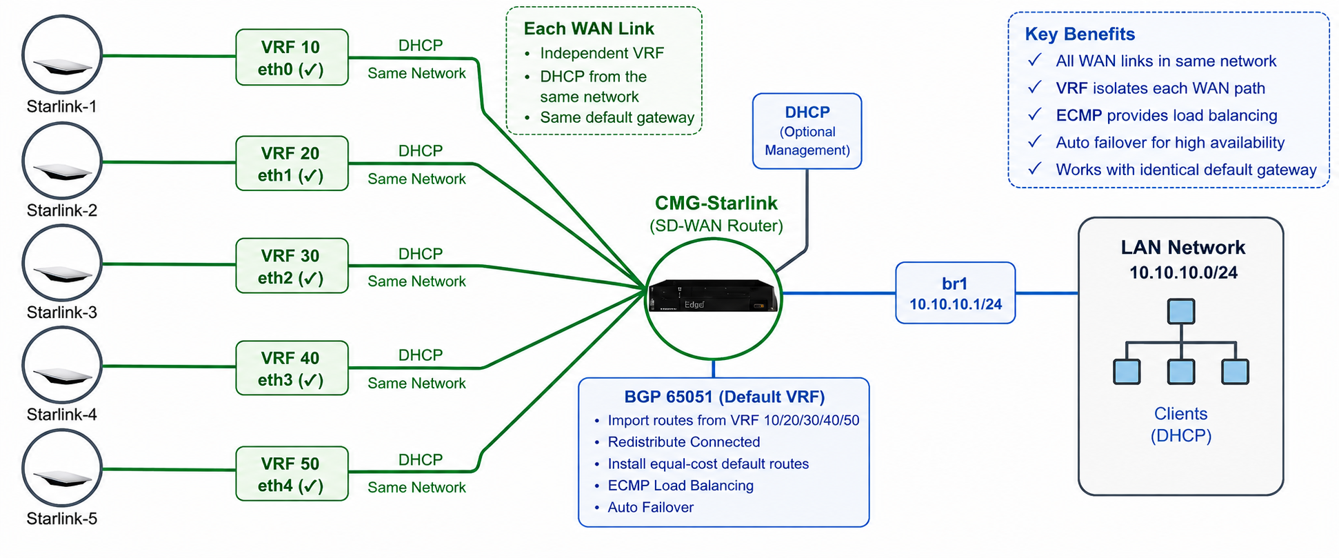
- Each WAN interface is placed into its own dedicated VRF. Because every VRF maintains a fully independent routing table, five interfaces can each hold an identical
0.0.0.0/0 via 100.64.0.1route at the same time without any conflict. - A BGP instance runs inside each per-link VRF, redistributing that link's DHCP-learned default route (a kernel route) into BGP, and importing the LAN subnet from the default VRF so return traffic has a path back to LAN clients.
- A BGP instance runs in the default VRF, importing every per-link VRF's BGP-redistributed default route. Because all of the imported default routes carry identical BGP attributes, the routing daemon installs them together as a single ECMP
0.0.0.0/0route — one route, multiple simultaneous nexthops, one per WAN link. - LAN traffic exiting through this ECMP route is load-shared across every currently healthy WAN link automatically. If a link's DHCP lease is lost or the interface goes down, its route disappears from the ECMP set and traffic redistributes across the remaining links — with no tracking configuration or manual failover logic involved.
Note
Although a BGP process runs in every VRF, no BGP neighbor is configured anywhere in this design — there is no external peer and no remote AS. BGP here is used purely as a local, intra-device mechanism (redistribute + import vrf) to move routes between VRFs on the same router. This is different from BGP's use elsewhere in RansNet SD-WAN (e.g. peering with an ISP in Dynamic Routing (BGP), or an iBGP session with a remote hub in VRF over SD-WAN) — everything in this design happens locally, on one device.
Key Characteristics
- All WAN links share one network — every link is issued an address (and gateway) from the same subnet, which is exactly what makes this design necessary instead of ordinary Multi-WAN.
- Each link is placed in its own VRF — VRF isolation is what allows multiple identical default routes to coexist on the same router without conflict.
- Traffic is load-shared across every healthy path — ECMP hashes flows across all available WAN links; with 5 equal-cost links, each carries roughly a fifth of total flows.
- Each flow always follows the same path — ECMP hashes a flow (by source/destination IP and port) to one link for its lifetime. A single flow's packets never split across links mid-session, avoiding reordering — but it also means one flow can never exceed a single link's bandwidth (see Best Practices — Performance).
- Automatic failover — losing a link removes its route from the ECMP set as soon as the kernel/BGP redistribution catches the change; flows hashed to the failed link re-hash onto a surviving link, while unaffected flows continue undisturbed.
Use Cases
| Scenario | Business Impact | Solution |
|---|---|---|
| Maritime, offshore, or remote sites with multiple Starlink terminals | A single satellite terminal has limited throughput and no redundancy; terminals from the same service plan share one gateway, defeating standard Multi-WAN | Bond terminals via VRF + ECMP for combined throughput and automatic terminal failover |
| Branch with multiple SIM-based WAN links on the same carrier | Multiple LTE/5G SIMs on one carrier/APN are issued addresses from the same pool with an identical gateway | The same VRF + ECMP bonding pattern applies to wwan interfaces |
| Sites with several fiber/broadband drops from one wholesale provider | The ISP hands out an identical gateway across all drops, so the links cannot be told apart by conventional routing | Bond all drops into one high-bandwidth uplink instead of running them as unrelated, individually under-used links |
| Temporary or event connectivity needing high bandwidth fast | A single link cannot meet demand, and adding more same-plan terminals is the fastest way to scale capacity | ECMP aggregates bandwidth across all terminals without any per-link traffic engineering |
Requirements
- A RansNet gateway-series router with enough usable ports for the number of WAN links being bonded (this guide uses a
CMGwitheth0–eth4for five links) - Each WAN uplink issued an address and default gateway via DHCP from the same underlying network
- A dedicated VRF ID reserved per WAN link (this guide uses
10/20/30/40/50) - A BGP AS number configured on the router for internal route leaking (this guide uses private AS
65051, consistent with other RansNet SD-WAN use cases) - A LAN interface (bridge or VLAN) that remains in the default VRF — only the WAN side is split into per-link VRFs
Network Behavior
Steady-State (All Links Healthy)
- All WAN links are up, each in its own VRF, each holding its own DHCP-learned
0.0.0.0/0route in its local per-VRF table. - BGP in the default VRF imports and installs all of them as ECMP nexthops of a single
0.0.0.0/0route. - LAN client flows are hashed across every link; aggregate outbound bandwidth approaches the sum of all healthy links.
Failover — One Link Goes Down
- The DHCP lease is lost or the interface goes down, so the kernel withdraws that link's default route.
redistribute kernelin that link's VRF stops advertising the route into BGP, so the default VRF'simport vrf <n>no longer sees it — the nexthop is removed from the ECMP set automatically.- Flows that were hashed to the failed link reconnect and re-hash onto a surviving link; flows already on other links are undisturbed.
- When the link recovers and DHCP reacquires a lease, the route reappears through the same chain and the ECMP set grows back to include it — no manual re-enable step is needed.
Configuration
Step 1 — Assign Each WAN Interface to Its Own VRF
Navigate to Device Settings → Network → Interfaces. For each WAN interface, configure DHCP addressing and assign a unique VRF ID — see VRF over SD-WAN — Configure LAN Interfaces for the equivalent GUI workflow (the same VRF-assignment field is used here for WAN interfaces instead of LAN).
interface eth0 vrf 10
 description "WAN Interface Starlink-1"
 enable
 ip address dhcp
!
interface eth1 vrf 20
 description "WAN Interface Starlink-2"
 enable
 ip address dhcp
!
interface eth2 vrf 30
 description "WAN Interface Starlink-3"
 enable
 ip address dhcp
!
interface eth3 vrf 40
 description "WAN Interface Starlink-4"
 enable
 ip address dhcp
!
interface eth4 vrf 50
 description "WAN Interface Starlink-5"
 enable
 ip address dhcp
!
Step 2 — Configure the LAN Bridge (Default VRF)
Unlike VRF over SD-WAN, where the LAN is moved into a service VRF, here the LAN stays in the default VRF — VRFs are used only to isolate the WAN side.
interface eth5
 enable
 bridge-group 1
!
interface eth6
 enable
 bridge-group 1
!
interface eth7
 enable
 bridge-group 1
!
interface bridge br1
 description LAN
 enable
 ip address 10.10.10.1/24
 dhcp-server
  router 10.10.10.1
  dns 8.8.8.8 8.8.4.4
  range 10.10.10.10 10.10.10.254
  enable
!
Step 3 — Redistribute and Import Routes in Each Per-Link VRF
Within each per-link VRF, redistribute the DHCP-learned kernel default route into BGP, and import the default VRF's routes so the link has a return path to LAN clients.
router bgp 65051 vrf 10
 redistribute kernel
 import vrf default
!
router bgp 65051 vrf 20
 redistribute kernel
 import vrf default
!
router bgp 65051 vrf 30
 redistribute kernel
 import vrf default
!
router bgp 65051 vrf 40
 redistribute kernel
 import vrf default
!
router bgp 65051 vrf 50
 redistribute kernel
 import vrf default
!
Note
redistribute kernel picks up the DHCP-installed 0.0.0.0/0 route on that VRF's interface and injects it into BGP within the same VRF — this is what makes the link's default route visible for the default VRF to import in the next step. import vrf default leaks the LAN subnet (10.10.10.0/24, redistributed connected below) into this VRF, giving return traffic addressed to LAN clients a path back out.
Step 4 — Redistribute and Import Routes in the Default VRF
router bgp 65051
 redistribute connected
 import vrf 10
 import vrf 20
 import vrf 30
 import vrf 40
 import vrf 50
!
Note
redistribute connected advertises the LAN subnet (10.10.10.0/24, from br1) into BGP so it can be leaked into each per-link VRF via import vrf default in Step 3. Each import vrf <n> pulls that link's BGP-redistributed default route into the default VRF's BGP table. Because all five imported default routes carry identical BGP attributes (same AS-path length and origin, with no differentiating local-preference or weight configured), the routing daemon installs all of them together as a single Equal-Cost Multi-Path (ECMP) 0.0.0.0/0 route — this is the mechanism that produces the load-balanced bonded uplink.
Step 5 — Firewall and NAT
The eth+ wildcard applies the outbound-permit and SNAT overload rule to every Ethernet WAN interface at once (eth0–eth4), so a new WAN link added later only needs Steps 1, 3, and one more import vrf line in Step 4 — the firewall and NAT rules already cover it.
Full Configuration Reference (CMG)
hostname STARLINK-CMG
!
interface eth0 vrf 10
description "WAN Interface Starlink-1"
enable
ip address dhcp
!
interface eth1 vrf 20
description "WAN Interface Starlink-2"
enable
ip address dhcp
!
interface eth2 vrf 30
description "WAN Interface Starlink-3"
enable
ip address dhcp
!
interface eth3 vrf 40
description "WAN Interface Starlink-4"
enable
ip address dhcp
!
interface eth4 vrf 50
description "WAN Interface Starlink-5"
enable
ip address dhcp
!
interface eth5
enable
bridge-group 1
!
interface eth6
enable
bridge-group 1
!
interface eth7
enable
bridge-group 1
!
interface bridge br1
description LAN
enable
ip address 10.10.10.1/24
dhcp-server
router 10.10.10.1
dns 8.8.8.8 8.8.4.4
range 10.10.10.10 10.10.10.254
enable
!
ip name-server 8.8.8.8 8.8.4.4
!
ip ntp-server time1.google.com time1.google.com
!
router bgp 65051
redistribute connected
import vrf 10
import vrf 20
import vrf 30
import vrf 40
import vrf 50
!
router bgp 65051 vrf 10
redistribute kernel
import vrf default
!
router bgp 65051 vrf 20
redistribute kernel
import vrf default
!
router bgp 65051 vrf 30
redistribute kernel
import vrf default
!
router bgp 65051 vrf 40
redistribute kernel
import vrf default
!
router bgp 65051 vrf 50
redistribute kernel
import vrf default
!
firewall-access 100 permit outbound eth+
!
firewall-snat 100 overload outbound eth+
!
Verification
| What to Check | Command | Expected Outcome |
|---|---|---|
| Per-link default route | show ip route vrf 10 (repeat for 20/30/40/50) |
Each VRF shows its own 0.0.0.0/0 kernel route via the shared DHCP gateway, plus the imported LAN subnet (10.10.10.0/24) via br1 (vrf default) |
| Bonded ECMP default route | show ip route vrf default |
A single B>* 0.0.0.0/0 route with one nexthop per healthy WAN link (via 100.64.0.1, eth0 (vrf 10), eth1 (vrf 20), etc.) |
| DHCP lease per link | show ip dhcp-lease |
Every WAN interface shows an active lease from the shared gateway |
| Real-world throughput | Run a speed test from a LAN client | Aggregate throughput approaches the sum of all healthy links' individual bandwidth — see example below |
Example output on gateway:
STARLINK-CMG# show ip route vrf all
Codes: K - kernel route, C - connected, S - static, R - RIP,
       O - OSPF, I - IS-IS, B - BGP, E - EIGRP, N - NHRP,
       T - Table, v - VNC, V - VNC-Direct, A - Babel, F - PBR,
       f - OpenFabric,
       > - selected route, * - FIB route, q - queued, r - rejected, b - backup
       t - trapped, o - offload failure

VRF 10:
K>* 0.0.0.0/0 [0/0] via 100.64.0.1, eth0, 05:17:39
B>* 2.1.2.1/32 [0/0] is directly connected, lo (vrf default), weight 1, 05:17:39
B>* 10.10.10.0/24 [0/0] is directly connected, br1 (vrf default), weight 1, 05:17:39
C>* 100.64.0.0/10 is directly connected, eth0, 05:18:36

VRF 20:
K>* 0.0.0.0/0 [0/0] via 100.64.0.1, eth1, 05:17:27
B>* 2.1.2.1/32 [0/0] is directly connected, lo, weight 1, 05:17:39
B>* 10.10.10.0/24 [0/0] is directly connected, br1 (vrf default), weight 1, 05:17:39
C>* 100.64.0.0/10 is directly connected, eth1, 05:17:27

VRF 30:
K>* 0.0.0.0/0 [0/0] via 100.64.0.1, eth2, 05:17:59
B>* 2.1.2.1/32 [0/0] is directly connected, lo, weight 1, 05:17:38
B>* 10.10.10.0/24 [0/0] is directly connected, br1 (vrf default), weight 1, 05:17:38
C>* 100.64.0.0/10 is directly connected, eth2, 05:18:00

VRF 40:
K>* 0.0.0.0/0 [0/0] via 100.64.0.1, eth3, 05:17:49
B>* 2.1.2.1/32 [0/0] is directly connected, lo, weight 1, 05:17:38
B>* 10.10.10.0/24 [0/0] is directly connected, br1 (vrf default), weight 1, 05:17:38
C>* 100.64.0.0/10 is directly connected, eth3, 05:17:50

VRF 50:
K>* 0.0.0.0/0 [0/0] via 100.64.0.1, eth4, 05:17:49
B>* 2.1.2.1/32 [0/0] is directly connected, lo, weight 1, 05:17:38
B>* 10.10.10.0/24 [0/0] is directly connected, br1 (vrf default), weight 1, 05:17:38
C>* 100.64.0.0/10 is directly connected, eth4, 05:17:49

VRF default:
B>* 0.0.0.0/0 [20/0] via 100.64.0.1, eth0 (vrf 10), weight 1, 05:17:38
                 via 100.64.0.1, eth1 (vrf 20), weight 1, 05:17:38
                 via 100.64.0.1, eth2 (vrf 30), weight 1, 05:17:38
                 via 100.64.0.1, eth3 (vrf 40), weight 1, 05:17:38
                 via 100.64.0.1, eth4 (vrf 50), weight 1, 05:17:38
C>* 2.1.2.1/32 is directly connected, lo, 05:17:48
C>* 10.10.10.0/24 is directly connected, br1, 05:17:45
STARLINK-CMG#
Confirm that:
- Each per-link VRF (
10–50) shows its own kernel-learned0.0.0.0/0and the imported LAN subnet - VRF default shows a single
0.0.0.0/0route with five nexthops, one per WAN link, each tagged with its originating VRF — this is the bonded ECMP route that all LAN-to-Internet traffic uses
Bonded Throughput Result
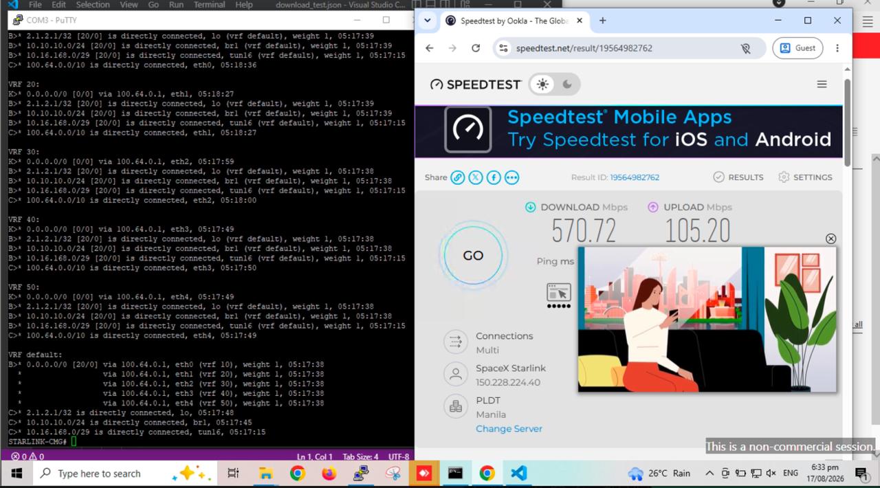
A speed test run from a LAN client behind the bonded gateway measured 570.72 Mbps download / 105.20 Mbps upload with multiple simultaneous connections — consistent with ECMP hashing the test's parallel connections across all five bonded terminals at once. A single-connection test would be limited to one link's bandwidth; see Best Practices — Performance.
Troubleshooting
| Symptom | Likely Cause | Solution |
|---|---|---|
| A single download/upload only achieves one link's worth of speed | ECMP hashes each flow to a single path; a single-connection transfer can only use one link's bandwidth | Use a multi-connection test (e.g. Speedtest, which opens several parallel connections) or generate traffic from multiple LAN clients to see the aggregate benefit |
show ip route vrf default shows fewer nexthops than expected for 0.0.0.0/0 |
One or more WAN links lost their DHCP lease, or the interface is down | Check show interface eth<n> for the affected link; verify the terminal/modem is powered and has signal |
A per-link VRF's default route is missing from show ip route vrf <n> |
DHCP has not completed on that interface, or redistribute kernel is missing from that VRF's BGP instance |
Confirm the lease with show ip dhcp-lease; confirm redistribute kernel is present under router bgp 65051 vrf <n> |
| LAN clients cannot reach the Internet through any link | The outbound firewall-access or SNAT rule is missing or doesn't match the WAN interfaces | Confirm firewall-access ... outbound eth+ and firewall-snat ... overload outbound eth+ are present and match all WAN interfaces |
| A newly added WAN link doesn't join the bonded pool | Missing VRF assignment on the interface, or the per-VRF BGP block/import vrf line was not added |
Repeat Steps 1, 3, and 5 for the new interface; add the matching import vrf <n> line under the default VRF's router bgp 65051 block (Step 4) |
Debugging Commands
STARLINK-CMG# show interface eth0
STARLINK-CMG# show ip dhcp-lease
STARLINK-CMG# show ip route
STARLINK-CMG# show ip bgp
Best Practices
Resilience
- Bond at least two links for redundancy; add more links for additional bandwidth and further redundancy.
- Terminals on the same shared plan can share correlated failure modes (e.g. a single weather event or obstruction affecting co-located dishes) — physically separate them where possible (different mounting locations or look angles).
- Periodically check
show ip route vrf defaultfor the full expected ECMP nexthop count; a silently dropped link still passes basic reachability checks within its own VRF but simply stops contributing to the bonded pool.
Performance
- ECMP load-balances per flow, not per packet — a single connection is capped at one link's speed. Multi-connection workloads (parallel downloads, many simultaneous LAN clients) are needed to realize the full aggregate bandwidth.
- Avoid bonding links with very different latency/jitter characteristics (e.g. one satellite link and one fiber link) in the same ECMP set — asymmetric per-path RTT makes individual flow performance inconsistent and harder to troubleshoot. Prefer bonding same-technology links, and use WAN Failover or standard Multi-WAN to prioritize a distinct, faster link ahead of a bonded pool used as backup capacity.
- Apply QoS on the LAN-facing bridge if specific traffic classes need guaranteed priority regardless of which bonded link they land on.
Scaling
- The pattern extends directly: add another
interface ethN vrf <new-id>(Step 1), a matchingrouter bgp 65051 vrf <new-id>block (Step 3), and one moreimport vrf <new-id>line under the default VRF's BGP instance (Step 4). The firewall/NAT rules already cover new interfaces via theeth+wildcard. - VRF IDs must be unique per device. If this router also participates in SD-WAN VPN overlays or VRF over SD-WAN, make sure VRF IDs used for WAN bonding don't collide with VRF IDs used for service VRFs elsewhere in the configuration.
Related Features
- WAN Failover Configuration — conventional Multi-WAN failover/load-balancing when WAN links sit on distinct subnets and gateways
- VRF over SD-WAN — the VRF and BGP route-leaking concepts used here, applied instead to LAN backhaul over an SD-WAN overlay
- Dual-WAN SD-WAN — combining WAN redundancy with a stable VPN overlay
- Dynamic Routing (BGP) — general BGP configuration and peering with an ISP
- Network Interfaces Configuration — interface and VRF assignment reference