Basic Internet Access Setup
Overview
This guide explains how to configure a RansNet router for basic Internet access. After completing this guide:
- WAN connectivity — The router obtains Internet access from your ISP
- LAN services — Local devices receive IP addresses automatically via DHCP
- Internet access — LAN users can access the Internet through the router's NAT firewall
Use Cases
This deployment is suitable for:
- Small offices — Branch locations with 10–50 users
- Retail shops — Point-of-sale systems and customer Wi-Fi
- Temporary sites — Construction, events, or short-term deployments
- Maritime cabins — Remote locations with 4G/5G backup
- Basic branch connectivity — Entry-level SD-WAN branch router
- Testing and lab environments — Development and proof-of-concept setups
Requirements
- RansNet router — Any model (HSA-520, UA-520, XE-300, or UAP-520)
- ISP modem or upstream Internet access — Fiber ONT, cable modem, or 4G/5G connection
- Ethernet cable — For connecting devices to LAN ports
- DHCP or static IP — ISP provides either dynamic (DHCP) or static IP on WAN link
- Optional: Wi-Fi — For wireless client connectivity (2.4 GHz and/or 5 GHz)
Topology Description
The basic setup consists of three network segments:
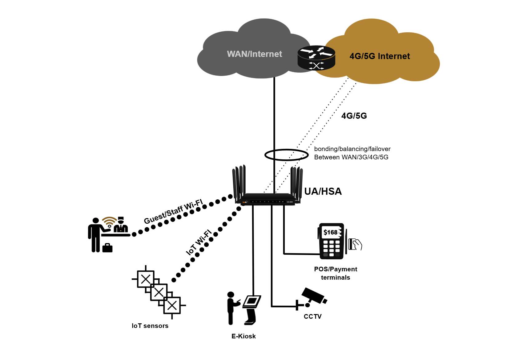
Key components:
- WAN (eth0) — Uplink to ISP; obtains IP via DHCP or static configuration
- LAN (vlan1) — Local network on ports LAN1–LAN4; default subnet is
192.168.8.0/22 - DHCP Server — Automatically assigns addresses to LAN clients in the range
192.168.8.10–192.168.11.254 - NAT/Firewall — Hides private LAN addresses and protects against unsolicited inbound traffic
- Optional Wi-Fi — Wi-Fi 0 (2.4 GHz) and Wi-Fi 1 (5 GHz) broadcast to the same LAN network
Configuration Methods
You can configure the router using either method:
- CLI via Console or SSH — Connect directly to the router's console port or SSH to its IP address. Refer to Device Bootstrapping for console access instructions.
- mFusion GUI — Provision the router through the mFusion management portal for centralized, web-based configuration. Refer to Device Provisioning for setup steps.
Refer to Getting Started for detailed device access and management instructions.
Note
RansNet routers ship with factory defaults that provide zero-touch provisioning, eg. out of the box, it provides Internet access and auto contacts RansNet cloud mfusion for remote orchestration.
The configuration steps below walk through these default settings and show where to customize them for your specific ISP and network. If you need to clear all configuration and reconfigure the router to start from scratch, enter enable mode and execute below cmd (Access the router via console only — SSH access will be lost after reboot.):
The router will reboot with a blank configuration, and you can reconfigure using the steps below.Step 1: Configure WAN Connection
The WAN (Wide Area Network) interface connects your router to the ISP link — typically a fiber ONT (Optical Network Terminal).
Refer to Ethernet Interfaces for detailed WAN port configuration.
DHCP Mode (Default)
Most ISP links use DHCP to assign the CPE (Customer Premises Equipment) a dynamic IP address and default route. This is the default configuration:
The router will receive a public (or private) IP address and automatically install a default route toward the ISP gateway.
Static IP Mode
If your ISP provides a static IP address, configure the interface with the static IP and install an explicit default route:
interface eth0
description "Connection to WAN"
enable
ip address 61.13.198.166/30
!
ip route 0.0.0.0/0 nexthop 61.13.198.165
Refer to Static Routes for complete static routing configuration details.
Cellular Backup
To use 4G/5G as a backup WAN link, enable the WWAN interface:
See WWAN Interfaces for SIM configuration, registration, and failover setup.
Step 2: Configure LAN and DHCP (and DNS)
The LAN (Local Area Network) is the private network serving users and devices. On HSA series routers, the default LAN (vlan1) includes all four LAN ports (LAN1 through LAN4). A static IP address on the LAN interface serves as the gateway for client devices, and the built-in DHCP server automatically issues private IP addresses and DNS server IPs to connected hosts.
interface vlan 1 1
description "Default VLAN for all LAN ports"
enable
ip address 192.168.8.1/22
dhcp-server
router 192.168.8.1
dns 8.8.8.8 8.8.4.4
range 192.168.8.10 192.168.11.254
enable
!
Refer to VLAN Interfaces for detailed VLAN configuration and switchport assignment for each VLAN.
Refer to DHCP Server for advanced DHCP options such as reserved leases, name servers, domain name assignment, and NTP configuration.
Step 3: Configure NAT/Firewall Rules
The RansNet router functions as a firewall, protecting your private network from unauthorized inbound traffic while allowing outbound access to the Internet. By default, all inbound connections are blocked.
Outbound Access Control
Permit outbound traffic on the WAN and cellular interfaces:
Source NAT (SNAT)
To hide your private LAN IP addresses from the Internet, the router translates outbound source IPs to the WAN interface IP. This masquerading allows return traffic to route back to the correct clients and enables bidirectional communication:
Refer to Firewall Policies for advanced access controls and object definitions.
Tip
The factory default configuration includes a firewall rule allowing SSH access from the LAN subnet (192.168.8.0/22) on port 22. This permits remote management via SSH from trusted LAN clients while blocking unsolicited inbound connections from the Internet. Never expose SSH or other management services to the WAN — restrict management access to the LAN only.
Step 4 (Optional): Configure Wi-Fi
Enable wireless connectivity to allow users to access the Internet without wired connections. Wireless clients are automatically assigned DHCP IP addresses from the same LAN subnet as wired clients (default VLAN1 for HSA/UA-520 series).
interface wifi 0
ssid corpnet
encryption WPA2-PSK key pskpassword
enable
!
interface wifi 1
ssid corpnet
encryption WPA2-PSK key pskpassword
enable
!
Refer to Wireless Interfaces for SSID configuration, encryption modes, channel selection, and multi-SSID setups.
Model-Specific Differences
This guide uses HSA-520 as the example. If you're using a different model, note these differences:
| Model | WAN Interface | LAN Ports | Notes |
|---|---|---|---|
| HSA-520 / UA-520 | eth0 | LAN1-4 on vlan1 | Standard setup as shown in this guide. |
| XE-300 | WAN/LAN1 (vlan2) | LAN2-4 on vlan1 | Important: XE-300 maps WAN to vlan2 and LAN to vlan1 (opposite of older versions). See XE-300 Default Configuration in release notes. |
| UAP-520 | eth0 | LAN1-4 on vlan1 | Similar to HSA-520; includes built-in access point. Wi-Fi configuration available on the device. |
Refer to Product Overview for complete hardware specifications and port assignments by model.
Factory Default Configuration
RansNet routers ship with a complete default configuration that provides immediate Internet connectivity without any manual changes. The configuration below shows the factory defaults for HSA-520 devices running out of the box:
!
hostname HSA-520
!
interface eth0
  description "Connection to WAN"
  enable
  ip address dhcp
!
interface eth1
description "DO NOT configure"
enable
!
interface vlan 1 1
description "Default VLAN for all LAN ports"
enable
ip address 192.168.8.1/22
dhcp-server
router 192.168.8.1
dns 8.8.8.8 8.8.4.4
range 192.168.8.10 192.168.11.254
enable
!
interface wwan0
  enable
!
ip name-server 8.8.8.8 8.8.4.4
!
firewall-input 100 permit all tcp src 192.168.8.0/22 dport 22
!
firewall-access 100 permit outbound eth0
firewall-access 101 permit outbound wwan+
!
firewall-snat 100 overload outbound eth0
firewall-snat 101 overload outbound wwan+
!
This default configuration enables: - WAN connectivity via DHCP on eth0 - LAN connectivity with private IP range 192.168.8.0/22 and DHCP server - Cellular backup with wwan0 enabled - Firewall protection with management access restricted to SSH (port 22) from the LAN subnet and outbound NAT masquerading - DNS resolution using Google's public DNS servers (8.8.8.8, 8.8.4.4)
No additional configuration is required for basic Internet access — simply connect the WAN port to your ISP link and connect client devices to the LAN ports or wireless network.
Verification and Testing
After completing the configuration, verify that all components are operational. Connect a PC to one of the LAN ports, and console/SSH to the router to run the tests below.
| Items to Test | Command | Expected Outcome |
|---|---|---|
| WAN Interface Status | show interface eth0 (fiber) or show interface wwan0 (cellular) |
Interface shows UP status with a valid IP address. For DHCP, IP is assigned by ISP; for static IP, matches your configuration. See Ethernet Interfaces Verification. |
| Default Route | show ip route |
Default route 0.0.0.0/0 exists with ISP gateway as next-hop or via cellular interface. See Static Routes Verification. |
| LAN Interface | show interface vlan1 |
Interface shows UP status with IP address 192.168.8.1/22. See VLAN Interfaces Verification. |
| DHCP Server Status | show ip dhcp-server |
DHCP server is enabled and running. See DHCP Server Verification. |
| DHCP Active Leases | show ip dhcp-lease |
Connected clients have IP addresses in range 192.168.8.10–192.168.11.254. |
| Firewall Access Rules | show firewall access-list |
Rules permit outbound traffic on eth0 and wwan+. See Firewall Policies. |
| NAT Rules | show firewall snat-list |
SNAT rules show overload (masquerading) configured for outbound interfaces. |
| Wireless Status (if configured) | show interface wifi |
Both 2.4 GHz and 5 GHz SSIDs show UP and are broadcasting. See Wireless Interfaces Verification. |
| Wireless Clients (if configured) | show interface wifi clients |
Connected clients appear with valid IP addresses from LAN range; signal strength (RSSI) is reasonable (-30 to -80 dBm). |
| Connectivity to ISP Gateway | ping <ISP-gateway-IP> |
Ping succeeds with reasonable latency (< 50 ms). |
| Connectivity to Public DNS | ping 8.8.8.8 |
Ping succeeds, confirming end-to-end Internet access. |
| DNS Resolution | nslookup google.com or dig google.com |
DNS queries resolve successfully and return IP addresses. Confirms DNS servers are reachable and responding. |
| Routing Path to Internet | traceroute www.google.com |
Traceroute shows path through ISP gateway to destination. |
| Internet Throughput | run speedtest |
Throughput is close to ISP provisioned speed (up to 1 Gbps on HSA, limited by ISP connection). |
Troubleshooting Common Issues
| Symptom | Likely Cause | Solution |
|---|---|---|
| WAN interface stays DOWN or doesn't get DHCP IP | ISP link not connected, or DHCP request rejected | Verify fiber/4G link is connected and active. Check ISP for DHCP relay or authentication requirements. Power cycle the router and ISP modem. |
| WAN has IP but no Internet access | Default route not installed, or ISP requires additional configuration | Run show ip route to confirm default route exists. Some ISPs require PPPoE or additional gateway configuration. |
| LAN clients don't receive DHCP leases | DHCP server not running or VLAN misconfigured | Verify DHCP is enabled in vlan1 config. Check that LAN ports are assigned to vlan1 using show interface switchport. |
| DNS resolution fails (nslookup times out) | DNS servers unreachable or not configured in DHCP | Verify DNS servers are configured in DHCP server section (dns 8.8.8.8 8.8.4.4). Test with ping 8.8.8.8 to confirm ISP link is working. |
| Clients connect to Wi-Fi but have no Internet | Wireless VLAN not bridged to LAN, or firewall rules blocking traffic | Verify wireless SSID is assigned to vlan1 (or the correct LAN VLAN). Check firewall access rules permit outbound traffic on eth0/wwan0. |
| Can't reach router management (192.168.8.1) | Router IP is different (static config overrode default), or LAN interface is down | Run show interface vlan1 to confirm the configured IP. Verify vlan1 is UP. Reconfigure if needed, or perform a factory reset. |
| Firewall blocking legitimate traffic | Firewall rules too restrictive or outbound rule missing | Run show firewall access-list to review rules. Ensure firewall-access rules permit the required traffic. By default, all inbound is blocked (intended). |
| Throughput lower than expected | MTU mismatch, interference (wireless), or ISP speed limitation | For PPPoE or certain ISP links, reduce router MTU to 1492. Check wireless signal strength and channel interference. Contact ISP to confirm provisioned speed. |
Best Practices & Configuration Notes
Time Synchronization (NTP)
The router uses NTP to maintain accurate system time, which is essential for certificate validation, logging, and scheduled tasks. Verify NTP is working:
The factory config uses the system default NTP servers. If your network is isolated, configure a local NTP server or manually set the time.
MTU Configuration
For most deployments, the default MTU of 1500 bytes is correct. However, some ISPs (particularly PPPoE) require MTU 1492:
- Fiber/Ethernet: MTU 1500 (default)
- PPPoE: MTU 1492 (reduces TCP throughput by ~4%)
- 4G/5G: Varies by carrier; typically 1500
If you experience packet fragmentation or connection issues, request your ISP's required MTU.
Performance Expectations
| Model | Firewall Throughput | VPN Throughput | Notes |
|---|---|---|---|
| HSA-520 | 1 Gbps | 200 Mbps (IPSec) / 300 Mbps (WireGuard) | Enterprise branch model; supports up to 100 concurrent devices. |
| UA-520 | 1 Gbps | 200 Mbps (IPSec) / 300 Mbps (WireGuard) | Premium branch with 5G support; 100 concurrent devices. |
| XE-300 | 100 Mbps | 10 Mbps (IPSec) / 20 Mbps (WireGuard) | Ultra-compact industrial IoT model; limited to 20 concurrent devices due to form factor. |
Actual throughput depends on ISP provisioning, firewall rule complexity, feature load (encryption, inspection, traffic shaping), and device capacity. For detailed specifications, refer to Product Overview.
Security Best Practices
- Never expose management services to WAN — SSH and GUI access are restricted to LAN by default. Maintain this configuration.
- Use strong passwords — Change default credentials and use passphrases for Wi-Fi encryption.
- Keep firmware updated — Deploy security patches promptly. Refer to Release Notes for available updates.
- Enable firewall logging (optional) — For troubleshooting, enable firewall logs:
firewall-input log,firewall-access log. - Restrict inbound access — The factory config blocks all inbound except SSH from LAN. Add rules only for required services.
- Device hardening — For comprehensive security hardening beyond basic setup, refer to Device Hardening for authentication, certificate management, and advanced security practices.
After all configuration and testing pass, under enable mode write memory to save your configuration.