Layer-2 SD-WAN (Hub and Spoke)
Overview
For most enterprises with distributed remote offices or outlets, remote sites connect back to the HQ or data centre via Layer-3 IP networks — through the public Internet, 4G/5G, MPLS, or private leased lines. Traditional SD-WAN solutions are optimised for Layer-3 (IP) connectivity. However, some deployments require Layer-2 extension across geographically distributed sites, such as:
- Extending VLANs across branches
- Preserving broadcast-based services (DHCP, mDNS, legacy protocols)
- Supporting VM mobility or live migration across sites
- Supporting industrial automation and OT networks that do not rely on TCP/IP routing
L2 over SD-WAN (also known as L2VPN or Ethernet VPN over SD-WAN) addresses these requirements by encapsulating Ethernet frames inside VXLAN tunnels. It also provides traffic isolation and enhanced network security by logically separating WAN and LAN traffic — WAN links use the default routing table (underlay) to establish tunnel connectivity, while LAN devices communicate through a private VLAN segment isolated from external reachability.
Common use cases for L2 over SD-WAN include:
- Factory automation and OT (Operational Technology) networks
- IoT or retail chains with centralised services
- Maritime and transportation systems
- VM or container mobility across data centres or sites
L2VPN also simplifies large distributed deployments in several important ways:
- No per-site address planning — unlike Layer-3 SD-WAN, there is no need to allocate subnets or manage routing per location. All sites share the same Layer-2 broadcast domain.
- Seamless device roaming — branch routers are transparent to LAN devices, acting as L2 switches in the data path. No IP reconfiguration is needed when devices move between sites or when hardware is swapped.
- Centralised firewall and policy — all LAN devices use the central gateway as their default gateway, enabling centralised inter-VLAN routing, firewall enforcement, and traffic inspection at the hub.
- Reduced attack surface — branch routers have no routable IP address exposed to internal LAN networks, making them invisible to network scanners and harder to exploit.
Key Technologies
| Layer | Technology | Role |
|---|---|---|
| Data plane | Multipoint VXLAN | Encapsulates Ethernet frames (including broadcast and multicast) for transport across the IP underlay |
| Underlay encryption | WireGuard or IPSec | Encrypts the outer IP tunnel between VXLAN Tunnel Endpoints (VTEPs) |
Configuration on Gateway
Most configuration is performed on the gateway via mfusion. The resulting configuration is automatically compiled and pushed to assigned branch routers.
This guide walks through the Hub-and-Spoke topology. In this topology:
- The system default routing table (underlay) is used to establish L2VPN tunnels over available WAN links. Configure WAN failover between links if redundancy is required.
- The VXLAN tunnel interface is bridged to the LAN interface, creating a flat Layer-2 network that spans from each branch to the gateway.
Step 1 — Configure LAN Interfaces
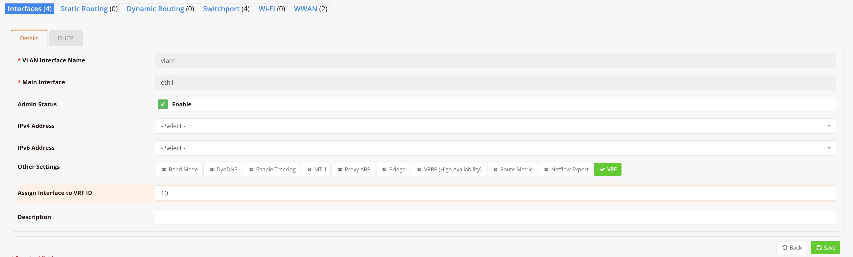
On both the gateway and each branch router, configure VLAN 1 as a Layer-2 interface (substitute VLAN 1 with your actual LAN or VLAN interface).
Note
No IP address is required on the LAN/VLAN interface — it will be bridged into the VXLAN tunnel in the next step.
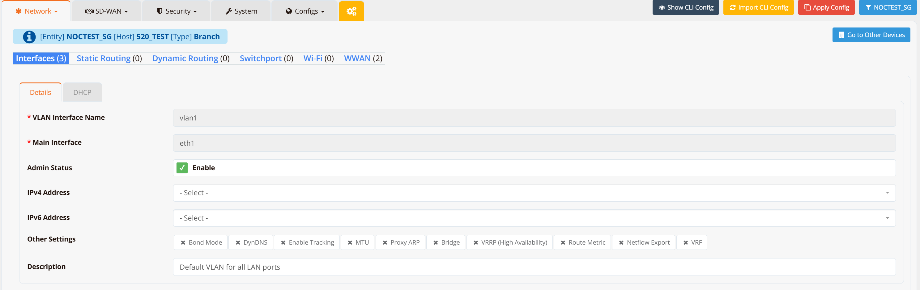
Navigate to Device → Interfaces → VLAN and create VLAN 1 without assigning an IP address.
Gateway
Branch Routers (repeat for each branch)
Step 2 — Configure SD-WAN VPN Instance
On the gateway, navigate to SD-WAN → VPN → Add VPN Instance. Select the VPN topology and encryption protocol.
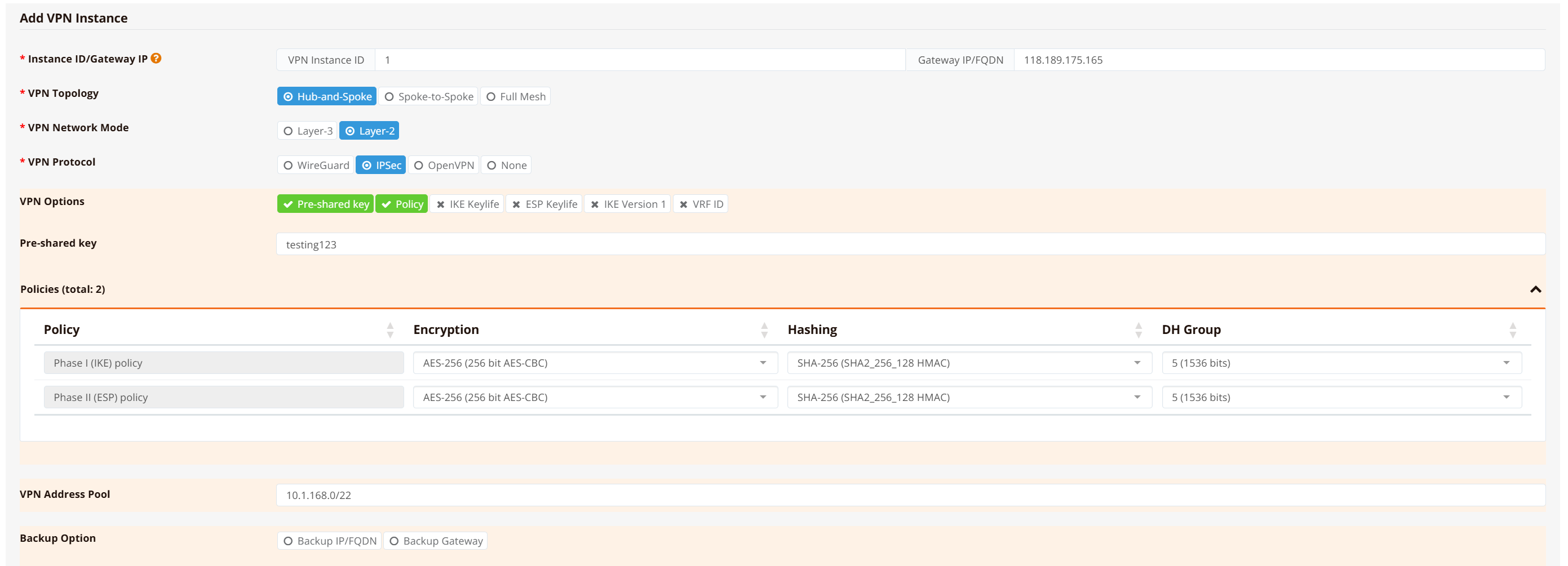
Select Hub-and-Spoke topology, Layer-2* network mode, and IPSec** as the encryption protocol.
Note
Hub-and-Spoke restricts spoke devices to communicate with the hub only — no spoke-to-spoke traffic. This is the recommended topology when inter-branch communication is not required, as it improves security and suppresses Layer-2 broadcast storms.
Bridge the VPN tunnel to the LAN interface, then click Continue, Save and Apply Config.
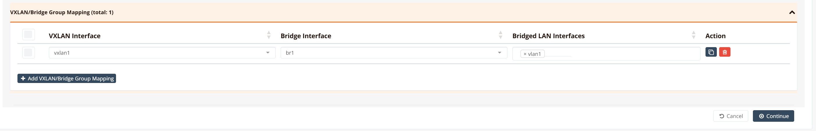
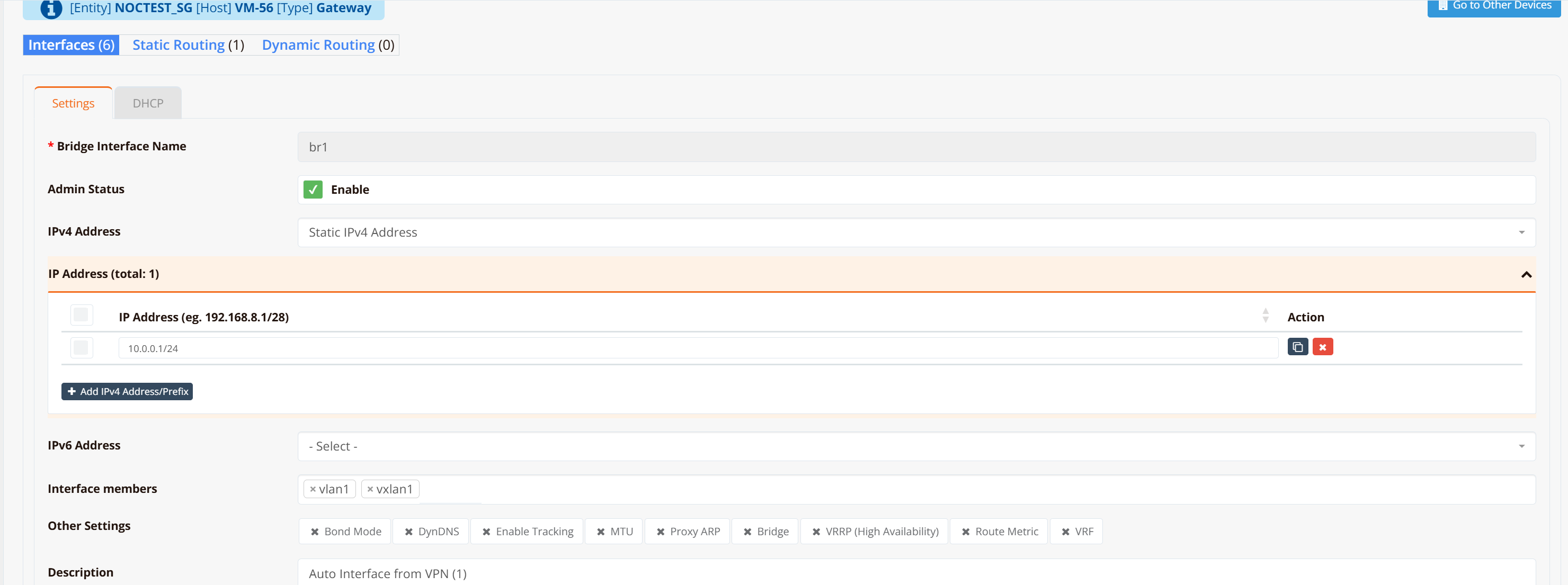
After the configuration is pushed, a br1 bridge and vxlan1 tunnel interface are automatically created on the gateway. If you need to bridge additional LAN/VLAN interfaces into the same tunnel, add them in the Bridged LAN Interfaces section.
Tip
For testing and verification, you can assign an IP address to the br1 interface to ping across the bridge and validate LAN-to-LAN reachability. In production deployments this is not required — LAN devices only need to be in the same subnet and will communicate as if attached to a single virtual Layer-2 switch.
Step 3 — Assign Branch Routers to VPN Instance
Scroll down in the VPN instance configuration, go to VPN Branches → Add VPN Branch, and select the branch routers to include. Repeat for all branch routers.
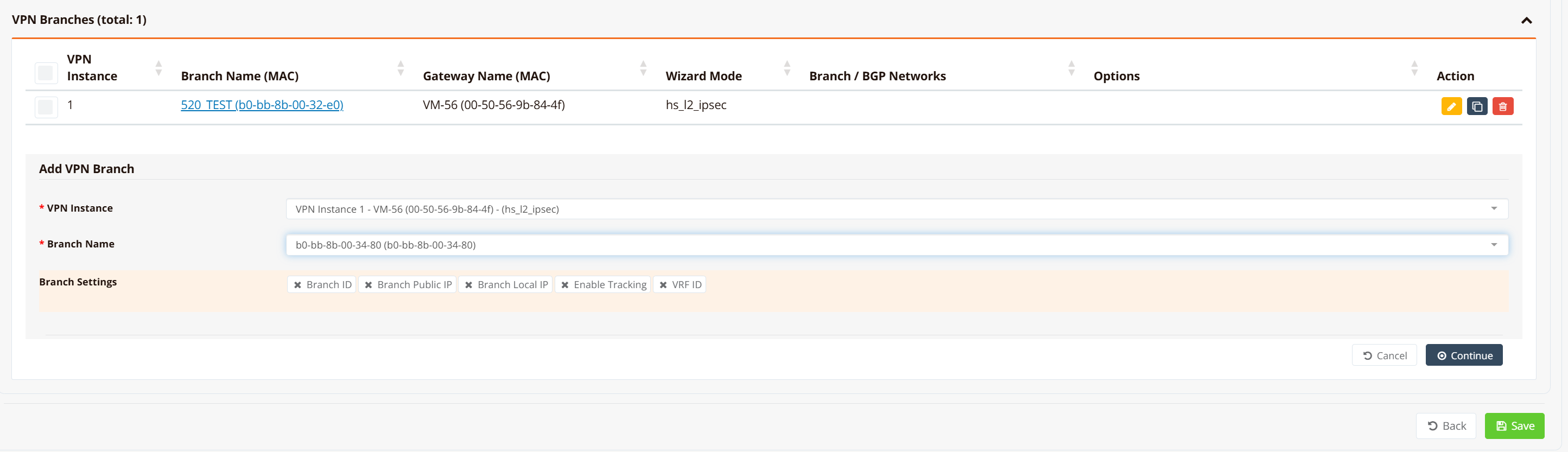
mfusion compiles and pushes the LAN/VLAN, bridge, VXLAN, and IPSec configuration to each branch automatically. No further manual configuration is required on branch devices.
Step 4 (Optional) — Assign IP Address to Gateway Bridge Interface
If the gateway router will act as the default gateway for all branch devices, assign an IP address to the br1 bridge interface. Optionally enable a DHCP server to issue IP addresses to branch devices across the L2 overlay.
Note
If an upstream firewall or DHCP server connects to the gateway's LAN/VLAN interface (which is bridged into the VPN tunnel), no IP address is required here. The gateway and branch routers act as a logical wire between branch devices and the upstream firewall — transparent to the data path.
CLI Reference (Gateway)
Note
SD-WAN configuration is generated automatically by mfusion. The CLI snippets below are provided for reference and troubleshooting only.
!
interface lo
 enable
 ip address 10.1.168.1/32
!
interface vxlan1
 description "Auto Interface from VPN (1)"
 vx-local 10.1.168.1
 enable
 bridge-group 1
!
interface vlan 0 1
 enable
 bridge-group 1
!
interface bridge br1
 description "Auto Interface from VPN (1)"
 enable
 ip address 10.0.0.1/24
!
ipsec ike-policy 1
 authentication psk
 policy AES-256 SHA-256 5
!
ipsec esp-policy 1
 policy AES-256 SHA-256 5
!
ipsec peer b0-bb-8b-00-32-e0
 local-net 10.1.168.1/32
 remote-id b0-bb-8b-00-32-e0
 remote-ip any
 remote-net 10.1.168.2/32
 policy ike 1 esp 1
 psk testing123
!
ipsec peer b0-bb-8b-00-34-80
 local-net 10.1.168.1/32
 remote-id b0-bb-8b-00-34-80
 remote-ip any
 remote-net 10.1.168.3/32
 policy ike 1 esp 1
 psk testing123
!
Key points:
- Each branch router is assigned a loopback IP (
10.1.168.x/32) used as the VXLAN local endpoint and IPSec tunnel identity. - The gateway loopback (
10.1.168.1) is the hub VTEP — all branches point their VXLANremoteto this address. - IPSec peers are identified by the branch MAC address (
remote-id), which allows branches behind NAT to register with a dynamic IP (remote-ip any). bridge-group 1on bothvxlan1andvlan 0 1places them into thebr1bridge, creating the Layer-2 overlay.
Configuration on Branch Routers
GUI Configuration
Branch router GUI configuration follows Step 1 — configure VLAN 1 as a Layer-2 interface without assigning an IP address. mfusion automatically generates and pushes all remaining tunnel and IPSec configuration to each assigned branch.
CLI Reference (Branch)
Note
Branch router configuration is auto-generated by mfusion. The CLI snippets below are provided for reference and troubleshooting only.
!
interface lo
 enable
 ip address 10.1.168.3/32
!
interface vxlan1
 description "Auto Interface from VPN (1)"
 vx-local 10.1.168.3 remote 10.1.168.1
 enable
 bridge-group 1
!
interface wwan0
 enable
!
interface vlan 1 1
 description "Default VLAN for all LAN ports"
 enable
 bridge-group 1
!
interface bridge br1
 description "Auto Interface from VPN (1)"
 bridge
 enable
!
ip name-server 8.8.8.8 8.8.4.4
!
ipsec ike-policy 1
 authentication psk
 policy AES-256 SHA-256 5
!
ipsec esp-policy 1
 policy AES-256 SHA-256 5
!
ipsec peer 118.189.175.165
 local-id b0-bb-8b-00-34-80
 local-net 10.1.168.3/32
 remote-net 10.1.168.1/32
 policy ike 1 esp 1
 psk testing123
!
Key points:
- Unlike the gateway, the branch VXLAN uses
vx-local <branch-lo> remote <hub-lo>— specifying the hub as the single remote VTEP. - The branch identifies itself to the gateway using its MAC address as the IPSec
local-id. - The branch has no explicit
remote-ipconfigured; it initiates the IPSec connection to the gateway's static IP (118.189.175.165). - No IP address is configured on
br1— the branch acts as a transparent L2 switch.
Verification
Gateway
Check IPSec peer status:
VM-56# show ipsec status
================================================================================
 IPSec Status
 Uptime  : 8 minutes, since Apr 24 12:47:41 2026
 Local   : 10.65.31.56, Gateway: 10.0.0.1
 Peers   : 2 established, 0 connecting
================================================================================

Peer                                State          Local Net         Remote Net             Tx       Rx  Uptime      IKE(Auth)    ESP
------------------------------------------------------------------------------------------------------------------------------------------------
b0-bb-8b-00-32-e0 (61.13.198.166)   ESTABLISHED    10.1.168.1/32     10.1.168.2/32          0B     816B  8 minutes   IKEv2(PSK)   AES-256/SHA256
b0-bb-8b-00-34-80 (61.13.198.166)   ESTABLISHED    10.1.168.1/32     10.1.168.3/32          0B     816B  8 minutes   IKEv2(PSK)   AES-256/SHA256

VM-56#
All branch peers should show ESTABLISHED. Each peer is identified by its MAC address, which is used as the remote identity in PSK authentication.
Check bridge membership:
VM-56# show interface bridge
  Bridge                 : br1
  Bridge ID              : 8000.c2017b8e3415
  STP                    : Disabled
  Member Interfaces      : vlan1 vxlan1

  Bridge                 : vxlan1
  STP                    : Disabled

VM-56#
Verify that both vxlan1 and vlan1 appear as members of br1. This confirms that the VTEP and LAN segment are correctly bridged.
Check VXLAN tunnel endpoint:
VM-56# show interface vxlan1
================================================================================
  Interface : vxlan1
================================================================================

  Network Information
  ----------------------------------------
  Admin State            : UP
  Link State             : UP
  MAC Address            : 76:7a:f0:30:39:43
  MTU                    : 1500 bytes
  IPv6 Address           : fe80::747a:f0ff:fe30:3943/64 [link]

  VXLAN Peers
  ----------------------------------------
a2:5c:9e:24:f0:75 master br1
a2:c9:10:5d:ea:bd master br1
76:7a:f0:30:39:43 vlan 1 master br1 permanent
76:7a:f0:30:39:43 master br1 permanent
a2:5c:9e:24:f0:75 dst 10.1.168.3 self
a2:c9:10:5d:ea:bd dst 10.1.168.2 self

  Physical Information
  ----------------------------------------
  Speed                  : Unknown!
  Duplex                 : Unknown! (255)
  Port Type              : Other
  Auto-Negotiation       : off
  Link Detected          : yes

================================================================================
VM-56#
The VXLAN Peers table shows each branch VTEP IP (10.1.168.2, 10.1.168.3) alongside the remote MAC address learned over the overlay. These entries confirm that the hub has established forwarding paths to each branch.
Branch Routers
Check IPSec peer status:
HSA-520# show ipsec status
================================================================================
 IPSec Status
 Uptime  : 20 minutes, since Apr 24 04:47:45 2026
 Local   : 10.18.18.94, Gateway: 10.194.71.166
 Peers   : 1 established, 0 connecting
================================================================================

Peer                                State          Local Net         Remote Net             Tx       Rx  Uptime      IKE(Auth)    ESP
------------------------------------------------------------------------------------------------------------------------------------------------
118.189.175.165 (118.189.175.165)   ESTABLISHED    10.1.168.2/32     10.1.168.1/32       2.0KB       0B  20 minutes  IKEv2(PSK)   AES-256/SHA256

HSA-520#
Each branch should have exactly one ESTABLISHED IPSec peer pointing to the hub gateway.
Check bridge membership:
HSA-520# show interface bridge
  Bridge                 : br-br1
  Bridge ID              : 7fff.a2c9105deabd
  STP                    : Disabled
  Member Interfaces      : vlan1 vxlan1

  Bridge                 : vxlan1
  STP                    : Disabled

HSA-520#
Check VXLAN tunnel endpoint:
HSA-520# show interface vxlan1
================================================================================
  Interface : vxlan1
================================================================================

  Network Information
  ----------------------------------------
  Admin State            : UP
  Link State             : UP
  MAC Address            : fe:6c:59:8e:30:e0
  MTU                    : 1500 bytes

  VXLAN Peers
  ----------------------------------------
fe:6c:59:8e:30:e0 master br-br1 permanent
00:00:00:00:00:00 dst 10.1.168.1 self permanent

  Physical Information
  ----------------------------------------
  Link Detected          : yes

================================================================================
HSA-520#
The entry 00:00:00:00:00:00 dst 10.1.168.1 self permanent is the default VXLAN forwarding entry that directs all unknown-destination traffic to the hub VTEP (10.1.168.1). This is expected in hub-and-spoke — branches forward all overlay traffic to the hub rather than learning direct peer-to-peer VTEP routes.
End-to-end LAN device test:
Connect a PC to the branch router's VLAN 1 port. Configure it with an IP address in the same subnet as the gateway bridge interface (for example 10.0.0.2/24) and ping the gateway bridge address (10.0.0.1). A successful response confirms that the Layer-2 path from the branch LAN through the VXLAN tunnel to the gateway bridge is fully operational.